Wide wave beam circular polarization micro-strip antenna
A microstrip antenna, circular polarization technology, applied in the direction of antenna, antenna grounding device, antenna grounding switch structure connection, etc., to achieve the effect of simple method, easy processing, and guaranteeing symmetry
- Summary
- Abstract
- Description
- Claims
- Application Information
AI Technical Summary
Problems solved by technology
Method used
Image
Examples
Embodiment 1
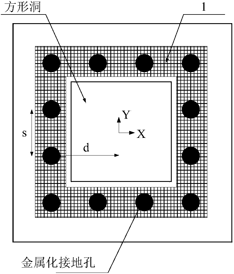
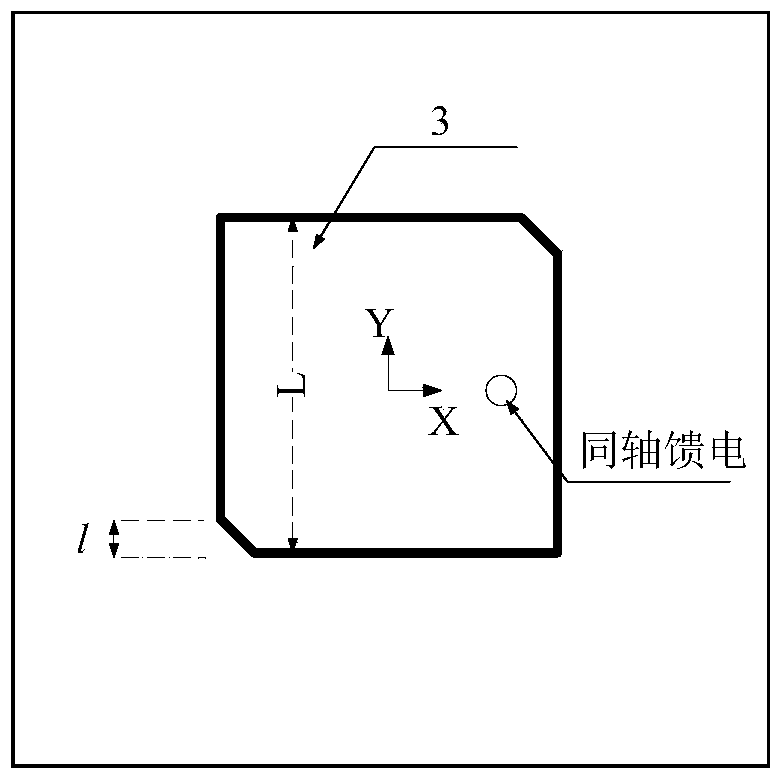
[0048] Such as Figure 6-8 As shown, the wide-beam circularly polarized microstrip antenna of the present invention is sequentially composed of a 3dB bridge, a microstrip antenna and an insulating cylinder with a metal patch from bottom to top. The microstrip antenna is composed of an antenna metal floor 5 , an antenna insulating plate 4 and an antenna metal patch 3 . The antenna metal floor 5 and the antenna metal patch 3 are square, and the cross section of the antenna insulating plate 4 is circular. The diameter of the antenna insulating plate 4 is much larger than the side length of the metal floor 5 for widening the beam width of the antenna, and the side length of the antenna metal patch 3 is smaller than the side length of the antenna metal floor 5 . With a certain height, an insulating tube 2 with a square ring cross section is placed on the insulating plate 4 of the microstrip antenna. The inner diameter of the insulating tube 2 is larger than the side length of the ...
Embodiment 2
[0054] Such as Figure 10 As shown, in this embodiment, the cross section of the insulating cylinder 2 and the metal patch 1 on its upper surface is a square ring, and the basic shapes of the antenna insulating plate 4, the antenna metal floor 5 and the antenna metal patch 3 are all square. The outer lengths of the insulating cylinder 2, the antenna insulating plate 4 and the antenna metal floor 5 are the same, both being 0.377λ. The width of the metal patch 1 is 0.027λ, and the outer length is 0.296λ. The thickness of the insulating cylinder 2 is 0.08λ, and the height is 0.161λ. The distance between the inner edge of the insulating cylinder 2 and the outer edge of the antenna metal patch 3 in the horizontal direction is 0.0183λ, and the distance from the inner edge of the metal patch 1 is 0.0134λ. Both the antenna insulation plate 4 and the insulation cylinder 2 are made of high-frequency dielectric materials with a dielectric constant of 6.15. The antenna has a beamwidth ...
Embodiment 3
[0057] Such as Figure 10 As shown, in this embodiment, the cross section of the insulating cylinder 2 and the metal patch 1 on its upper surface is a square ring, and the basic shapes of the antenna insulating plate 4, the antenna metal floor 5 and the antenna metal patch 3 are all square. The outer lengths of the insulating cylinder 2, the antenna insulating plate 4 and the antenna metal floor 5 are the same, both being 0.366λ. The width of the metal patch 1 is 0.0261λ, and the outer length is 0.293λ. The thickness of the insulating cylinder 2 is 0.0758λ, and the height is 0.157λ. The distance between the inner edge of the insulating cylinder 2 and the inner edge of the metal patch 1 in the horizontal direction is 0.0131λ, and the distance from the outer edge of the antenna metal patch 3 is 0.0157λ. Both the antenna insulation plate 4 and the insulation cylinder 2 are made of high-frequency dielectric materials with a dielectric constant of 6.15. The microstrip antenna us...
PUM
 Abstract
Description
Claims
Application Information
 - R&D
- Intellectual Property
- Life Sciences
- Materials
- Tech Scout
- Unparalleled Data Quality
- Higher Quality Content
- 60% Fewer Hallucinations
Browse by: Latest US Patents, China's latest patents, Technical Efficacy Thesaurus, Application Domain, Technology Topic, Popular Technical Reports.
© 2025 PatSnap. All rights reserved.Legal|Privacy policy|Modern Slavery Act Transparency Statement|Sitemap|About US| Contact US: help@patsnap.com


