

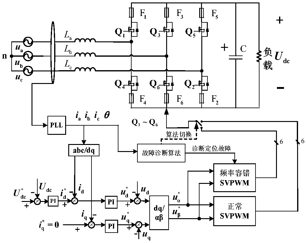
Fault-tolerant control method for two-level PWM rectifier based on switching frequency
A switching frequency, fault-tolerant control technology, applied in the output power conversion device, the conversion of AC power input to DC power output, electrical components and other directions, can solve the problem of undercompensation, fault-tolerant control effect is not optimal, unable to achieve multiple bridge arms Switch tube fault tolerance control and other issues
- Summary
- Abstract
- Description
- Claims
- Application Information
AI Technical Summary
Problems solved by technology
Method used
Image

Examples
Embodiment 1
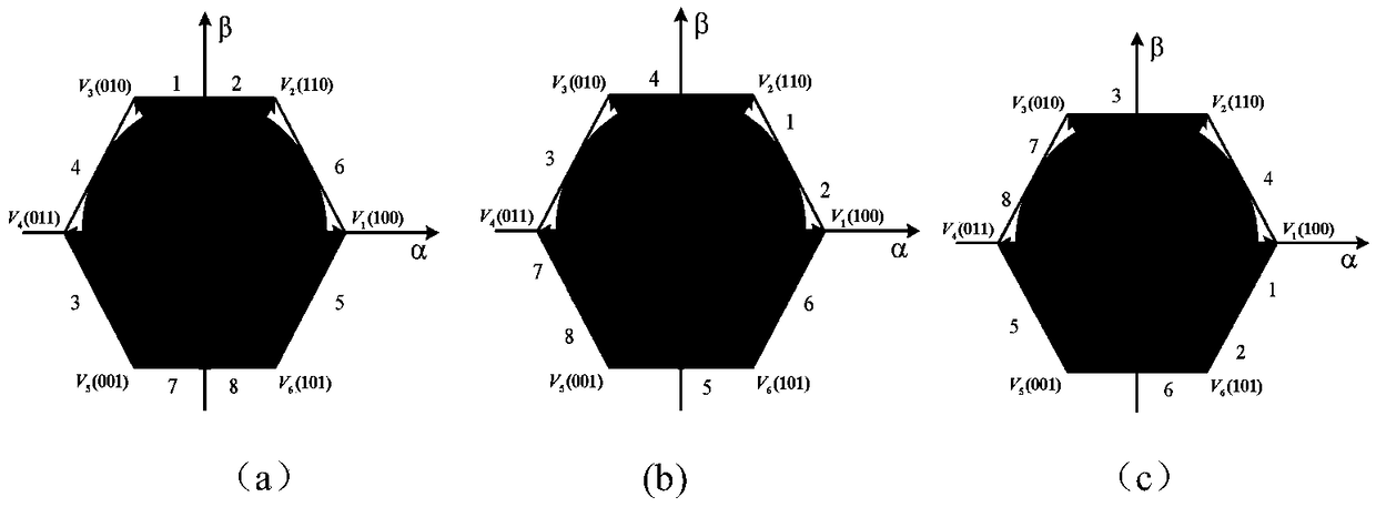
[0154]In this embodiment, the three-phase two-level PWM rectifier is divided into eight sectors to illustrate the single-tube fault Q1. When a short-circuit fault occurs in the Q1 tube, it will be converted into an open-circuit fault by the thermal fuse. When an open-circuit fault occurs in Q1 , according to the state analysis of the three-phase two-level PWM rectifier in the eight-sector division mode under the fault of the Q1 switching tube in Table 16, the frequency fault-tolerant control method is described.
[0155] Table 16 Analysis of PWM rectifier eight-sector single-cycle state under Q1 switch tube failure
[0156]
[0157] The schematic diagram of the sector distribution affected by the fault switch tube of the three-phase two-level PWM rectifier Q1 tube fault in the eight-sector division mode is as follows: Figure 5 As shown, in the case of Q1 tube failure, for the sectors not affected by the fault switch tube in Table 16, the normal reference voltage rotation v...
Embodiment 2
[0159] This embodiment is described by taking a three-phase two-level PWM rectifier with multi-transistor faults in an eight-sector division mode.
[0160] When two switching tubes in the three-phase two-level PWM rectifier fail at the same time, such as figure 1 As shown, it will be divided into the following four situations:
[0161] a. The two upper and lower switching tubes of the same bridge arm fail at the same time;
[0162] b. Two upper tubes of different bridge arms fail at the same time;
[0163] c. Two lower tubes of different bridge arms fail at the same time;
[0164] d. One upper tube and one lower tube of different bridge arms are faulty.
[0165] Since the short-circuit fault can be converted into an open-circuit fault through the thermal fuse, after other fault diagnosis, the switching tube fault can also be converted into an open-circuit fault by turning off the controller. Here, the open-circuit fault is used for description.
[0166] For case a, the sim...
Embodiment 3
[0174] In this embodiment, the three-phase two-level PWM rectifier is divided into twelve sectors with a single-tube fault Q1 for illustration. When a short-circuit fault occurs in the Q1 tube, it will be converted into an open-circuit fault by the thermal fuse. When an open-circuit fault occurs in Q1 , the frequency fault-tolerant control method is described according to the state analysis of the three-phase two-level PWM rectifier in the twelve-sector division mode under the failure of the Q1 switch tube in Table 18.
[0175] Table 18 Single-cycle state analysis of twelve sectors of PWM rectifier under the fault of Q1 switching tube
[0176]
[0177] The schematic diagram of the sector distribution affected by the fault switch tube of the three-phase two-level PWM rectifier Q1 tube fault in the twelve-sector division mode is as follows: Figure 7 As shown, in the case of Q1 tube failure, for the sectors not affected by the fault switch tube in Table 18, the normal referen...
PUM
 Abstract
Description
Claims
Application Information