Eureka AIR delivers breakthrough ideas for toughest innovation challenges, trusted by R&D personnel around the world.

Inner cap attachment-detachment structure, and container equipped with same

A technology of structure and container, applied in the detachable structure of the inner cover and the container field with the detachable structure of the inner cover, can solve the problems of insufficient rigidity, falling, increased shaking, etc., and achieve stable and accurate engagement, The effect of stable bolt closing operation and reliable bolt closing operation

Active Publication Date: 2018-12-21
古野 有己
View PDF9 Cites 0 Cited by
  • Summary
  • Abstract
  • Description
  • Claims
  • Application Information

AI Technical Summary

Problems solved by technology

[0006] That is, of course, when the inner cover is inserted in a plug state reaching the opening of the container, it is restricted by the opening of the container, and the exact size and shape appear, and the detachment operation portion of the outer cover acting on such an inner cover performs a corresponding size. Therefore, if the unreliable action caused by the previously described gap is removed, the removal of the inner cover may become reliable
However, on the other hand, the inner cover, which is opened and free, has a shape that can be said to bulge compared with the closed and closed action state, and its rigidity is not sufficient. The engaged state between becomes a state that can be said to be loose, that is, a state in which shaking is increased
In this state, if the inner cover is to be closed again, the center of the inner cover and the center of the outer cover are inconsistent, and the inner cover cannot be evenly attached to the opening, and the pressing action may not be performed reliably, or Unreliable use conditions such as the outer cover that is being pressed into the inner cover falls into the depression of the inner cover

Method used


Image

  • Inner cap attachment-detachment structure, and container equipped with same
  • Inner cap attachment-detachment structure, and container equipped with same
  • Inner cap attachment-detachment structure, and container equipped with same

Examples


Embodiment

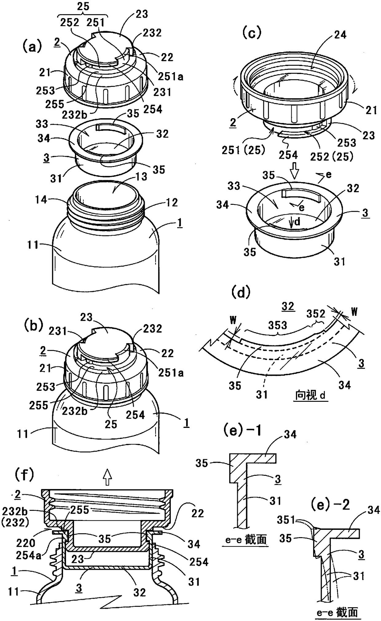
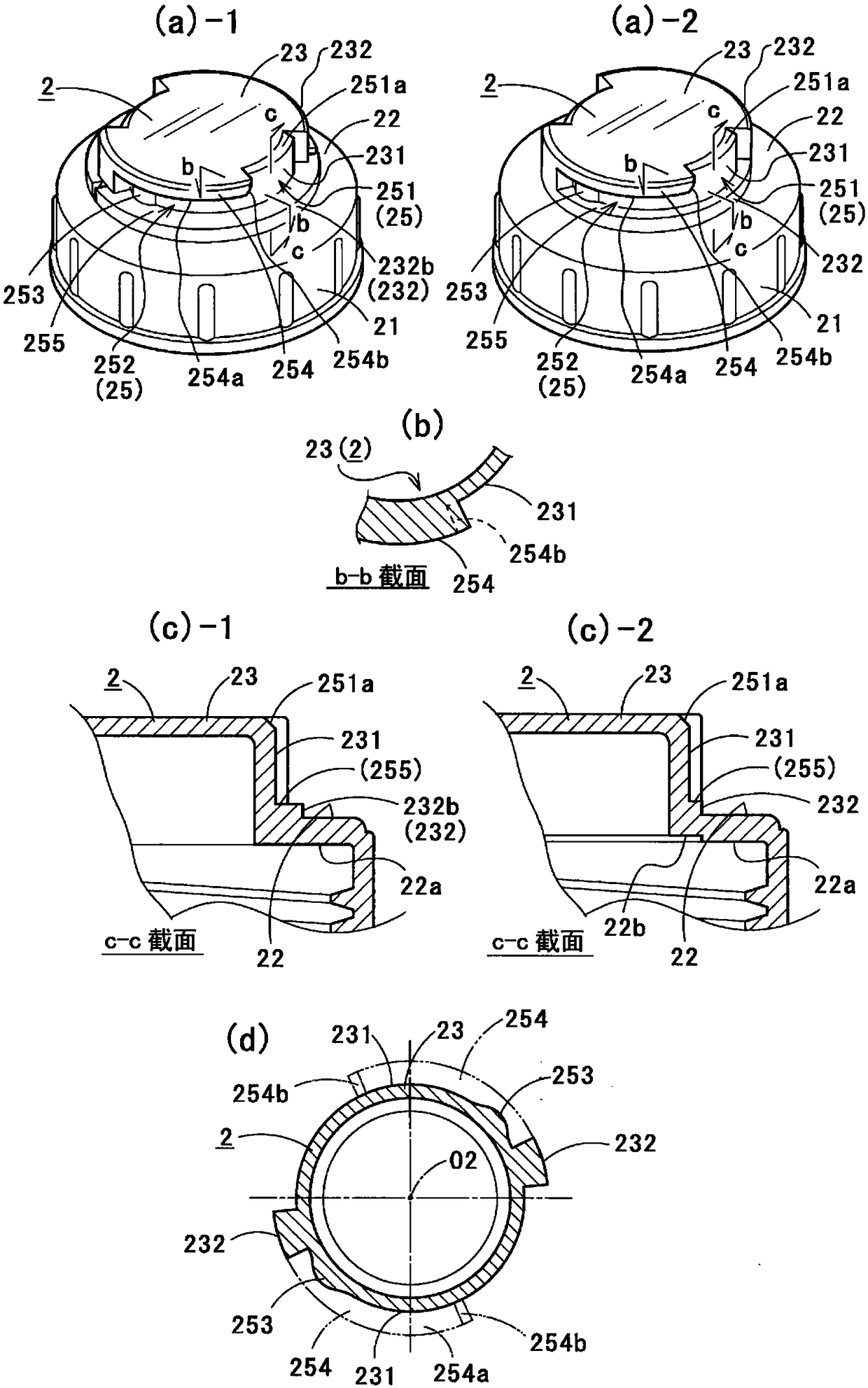
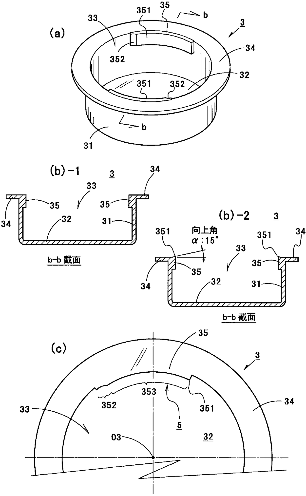
[0061] The reference numeral 1 in the figure is a container. The container includes an outer lid 2 and an inner lid 3, and a tightly sealed state is obtained by these members. That is, a fixing means is adopted in which the inner lid 3 is inserted in a plug shape to close the opening 13 of the container 1, and the outer lid 2 is screwed into the container 1 so as to cover the inner lid 3.

[0062] Hereinafter, each member will be described. In the container 1, as an example, a lid fitting portion 12 is provided on the container main body portion 11 that substantially stores the contents. The lid fitting portion 12 substantially forms an opening 13, is formed in a relatively short cylindrical shape, and becomes an opening 13 whose inside communicates with the container body 11. In addition, a male screw part 14 is formed on the outer peripheral part of the cover fitting part 12 by screwing in to fix the outer cover 2 as an example.

[0063] Next, the outer cover 2 will be explained...


PUM


Abstract

To further improve an inner cap attachment-detachment structure previously created by the present inventor, and provide a structure with which it is possible to eliminate uncertain operation even while considering and pursuing realistic manufacturing costs. The present invention is an inner cap attachment-detachment structure in which a container 1 is capped by a plug-like inner cap 3 and an outercap 2 mounted to the inner cap 3 so as to be externally overlaid thereupon, and the outer cap 2 is used as a hand tool to attach / detach the inner cap 3 to / from the container 1 in the manner of a bayonet connection. In particular, said structure is characterized in that: the inner cap 3 is equipped with a recessed part 33 for receiving an attachment-detachment operation part 23 of the outer cap 2;an engagement projection 35 is formed in a plurality in the upper area of the recessed part, and projects toward the inner side of the recessed part; a pressing surface 255 of the attachment-detachment part 23 is formed so as to press a plug body 31 of the inner cap 3 from above while in a state of engagement with the inner cap 3; and the engagement projection 35 is formed such that the upper position of a projection tip end 351 is higher than the height of the upper end of the plug body 31 in a vertical cross-sectional view.

Description

Technical field [0001] The present invention relates to a detachable structure of an inner lid in a container provided with an inner lid and an outer lid, and a container provided with the detachable structure of the inner lid. Background technique [0002] In order to strictly protect the contents, a container is used that includes an inner lid that plugs the opening of the container in a plug-like manner in order to improve airtightness and an outer lid that is provided on the inner lid in an externally covering state. In such a container, the inner lid is extremely tightly plugged into the opening in the form of a plug. Therefore, the operation of removing and inserting the inner lid is extremely difficult from experience. As a result, every time the inner cover is detached and assembled, the contents are likely to be scattered and the like. In addition, when the content is liquid, the removed inner cover often has the content attached to the bottom, and must be placed in an ...

Claims


Application Information

Patent Timeline
Patent Type & Authority Applications(China)
IPC IPC(8): B65D51/24B65D39/04B65D51/18B67B7/02
CPCB65D39/04B65D51/18B67B7/02B65D2251/0015B65D2251/0075B65D50/067
Inventor 古野有己
Owner 古野 有己
Why Eureka
Eureka Blog
Learn More