A silicon wafer rolling friction pair and rolling friction simulation method on the mesoscopic scale
A rolling friction and silicon wafer technology, applied in the field of friction and wear, can solve the problems of inability to accurately simulate rolling and wear conditions, and achieve the effect of saving research costs, simple structure of parts, and accurate simulation.
- Summary
- Abstract
- Description
- Claims
- Application Information
AI Technical Summary
Problems solved by technology
Method used
Image
Examples
Embodiment 1
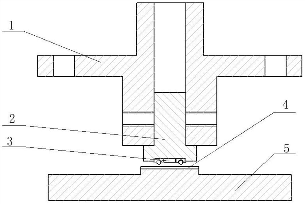
[0043] A specific embodiment of the present invention discloses a silicon chip rolling friction pair on the mesoscopic scale, including: a rolling ball plate 3 and a silicon chip 4, specifically, the silicon chip 4 is fixed on the base 5, and the rolling ball plate 3 is Surface contact between the rolling ball 33 and the silicon wafer 4, the base 5 is driven to rotate by the test machine, when the silicon wafer 4 rotates synchronously with the base, the rolling ball 33 rolls relative to the silicon wafer 4, and a rolling motion is formed between the rolling ball 33 and the silicon wafer 4. friction pair.
[0044] The rolling ball disc 3 is installed on the upper fixture, specifically, the rolling ball disc 3 is installed on the clamp body 1 through the pin shaft 2 .
[0045] The upper clamp is a detachable structure, including: a clamp body 1 and a pin shaft 2 . Specifically, the clamp body 1 and the pin shaft 2 are fixed by pins or screws, and a through hole with a diameter ...
Embodiment 2
[0078] The difference between this embodiment and the first embodiment is that the cage 32 is provided with a circular ball mounting track, and a plurality of rolling balls 33 are installed in the ball mounting track of the cage 32 . Such as Figure 9 As shown, the cage 32 includes an outer ring and an inner ring. A first rolling ball installation groove with an arc-shaped cross section is provided on the inner side of the outer ring, and a second rolling ball installation groove with an arc-shaped cross-section is provided on the outer side of the inner ring.
[0079] Specifically, the inner ring and the outer ring are concentric, and the first rolling ball installation groove and the second rolling ball installation groove jointly constitute the above-mentioned rolling ball installation track, and the rolling ball 33 can rotate in the rolling ball installation track of the cage 32 and Do overall circumferential rotation.
Embodiment 3
[0081] This embodiment provides a method for simulating rolling friction, using the silicon wafer rolling friction pair of Embodiment 1 or Embodiment 2, comprising the following steps:
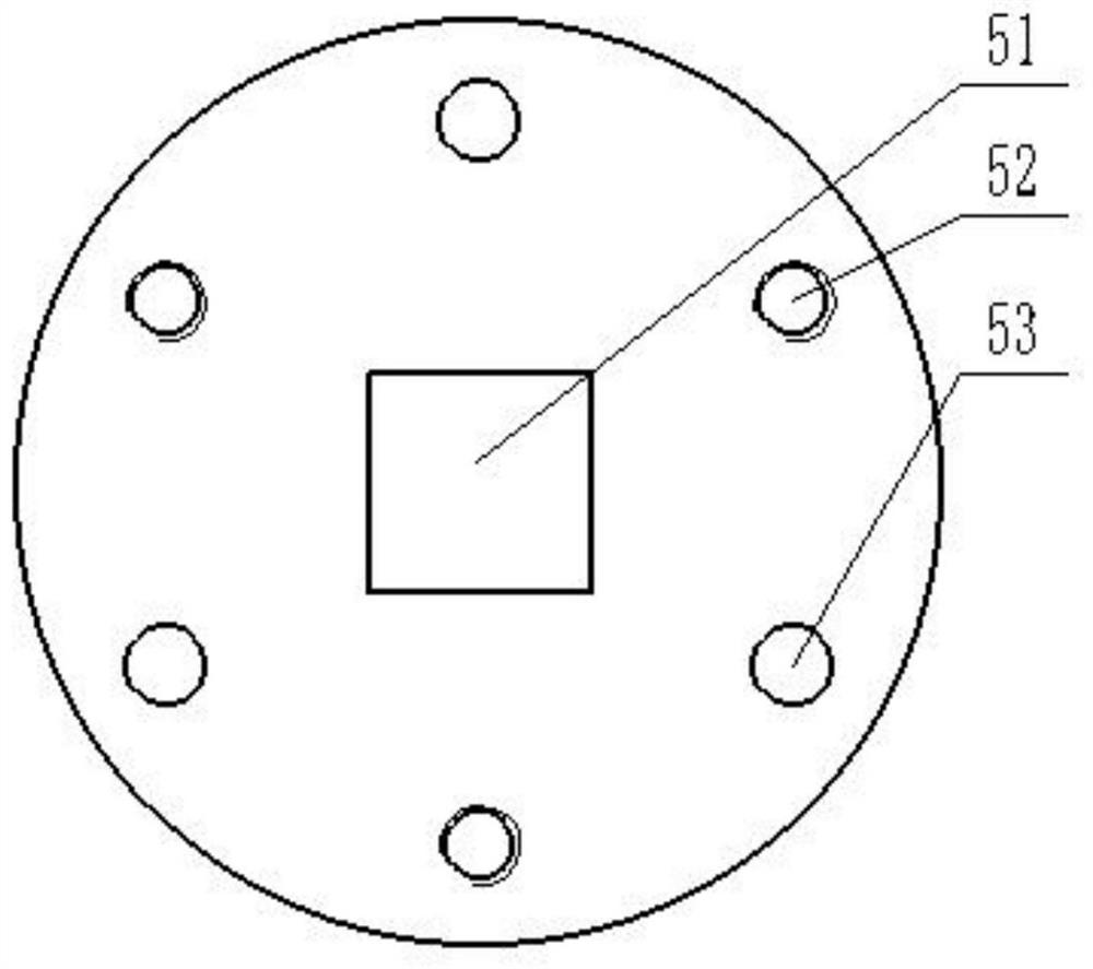
[0082] Step S1: Before the experiment starts, evenly coat the rough surface of the silicon wafer 4 to be tested with glue, and stick it on the platform 51 of the base 5, the base 5 is fixedly installed on the chassis of the testing machine, and the limiting structure 6 is set on the platform 51 And the periphery of the silicon wafer 4, and fixedly connected with the base 5, the silicon wafer 4 is limited by the limit structure 6, so as to prevent the silicon wafer 4 from slipping relative to the base 5, and prevent the failure of the experiment caused by degumming.
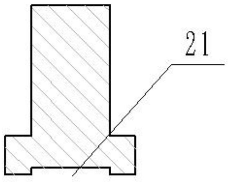
[0083] Step S2: There is a groove 21 at the bottom of the pin shaft 2, and the rolling ball disc 3 is clamped in the groove 21 of the pin shaft 2 through interference fit, so as to realize the tight fitting connection between the p...
PUM
| Property | Measurement | Unit |
|---|---|---|
| size | aaaaa | aaaaa |
Abstract
Description
Claims
Application Information
 - R&D
- Intellectual Property
- Life Sciences
- Materials
- Tech Scout
- Unparalleled Data Quality
- Higher Quality Content
- 60% Fewer Hallucinations
Browse by: Latest US Patents, China's latest patents, Technical Efficacy Thesaurus, Application Domain, Technology Topic, Popular Technical Reports.
© 2025 PatSnap. All rights reserved.Legal|Privacy policy|Modern Slavery Act Transparency Statement|Sitemap|About US| Contact US: help@patsnap.com


