Eureka AIR delivers breakthrough ideas for toughest innovation challenges, trusted by R&D personnel around the world.

Switching device for a gearbox

A technology of shifting device and gearbox, applied in the direction of transmission control, components with teeth, belt/chain/gear, etc., can solve problems such as increasing the difficulty of piston rod and hindering embedding.

Active Publication Date: 2012-08-22
ZF FRIEDRICHSHAFEN AG
View PDF7 Cites 0 Cited by
  • Summary
  • Abstract
  • Description
  • Claims
  • Application Information

AI Technical Summary

Problems solved by technology

[0004] The disadvantage of the prior art is that when the gearbox adjuster is installed, the actuating element arranged by the adjustment principle can move again, which makes it more difficult for the piston rod to engage in the pocket of the selector rod, or prevents it from engaging

Method used


Image

  • Switching device for a gearbox
  • Switching device for a gearbox

Examples


Embodiment Construction

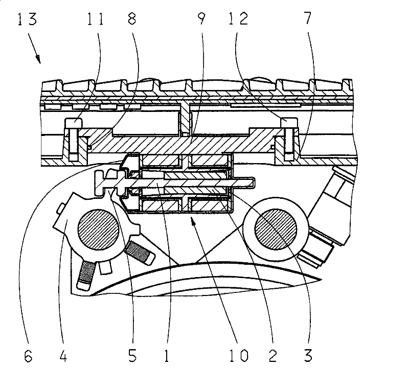
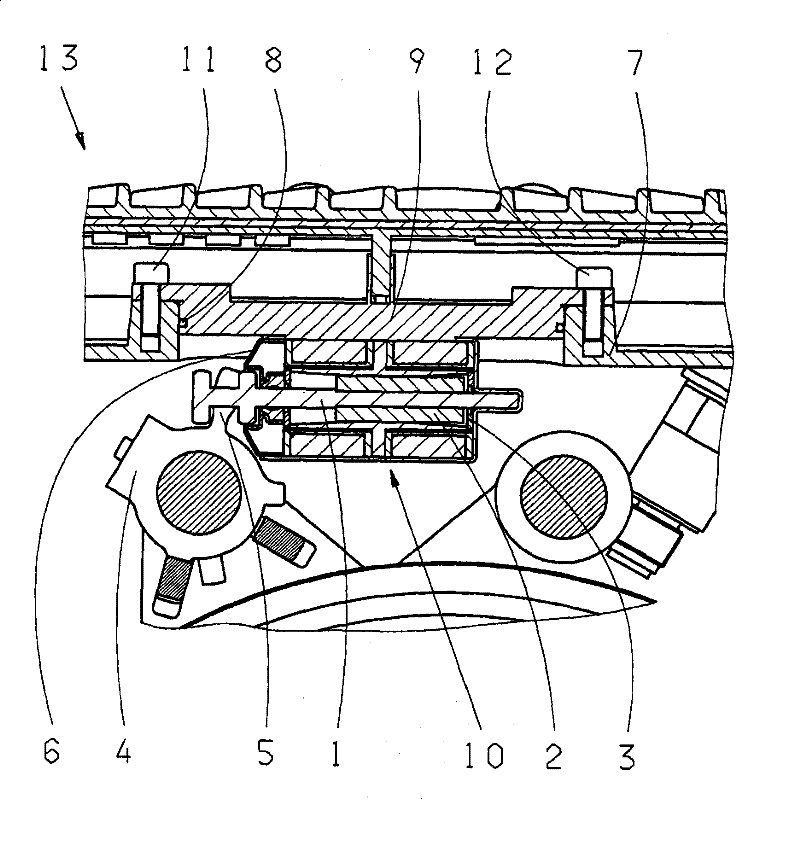
[0013] The single figure shows a partial view of the shifting device 13 for shifting the transmission. The armature 1 of the selection actuator 10 consists of a permanent magnet 2 . When installing the selection actuator, the armature 1 of the selection actuator 10 is connected to the drive cam 5 of the selection plate 4 . Fixing of the armature 1 in a position suitable for mounting the selector actuator 10 is achieved in such a way that the end stop 3 of the selector actuator 10 is made of a ferromagnetic material on which the permanent magnet 2 is attracted (forced end position fixed). For mounting the optional actuator 10 , therefore, no further means are required for securing the end position of the armature 1 . The gearbox is shifted to a specified gear before installing the selection actuator 10, so that the driving boss 5 of the selection plate 4 that must be embedded in the armature 1 of the selection actuator 10 can be seen from the outside. The conical element 6 i...


PUM


Abstract

The invention relates to a switching device (13) for a gearbox, comprising actuators for switching and selecting, the selection process being carried out by a selector actuator (10), connected to a driving lug (5) on a selector plate (4). The armature (1) of the selector actuator (10) is made from permanent magnets (2). The end stops (3) of the selector actuator (10) are made from a ferromagneticmaterial, the armature (1) of the selector actuator (10) being fixed in a defined position for assembly of the selector actuator (10).

Description

technical field [0001] The invention relates to a shifting device for a multi-speed shifting gearbox. Background technique [0002] An automatic shift transmission consists, in its main components, of an ordinary, sometimes also manually operated shift gearbox, in which the operation of the shifting clutch and / or starting clutch between the drive motor and the gearbox and the selection of the gearbox gears and gear changes are carried out automatically via the corresponding operating elements. These operating elements are usually designed as hydraulically or pneumatically actuatable servo cylinders or as electrical actuators, which act on the actuators for the gearbox functions. The actuator can be arranged on or in the gearbox. Wherein the main gearbox can be designed in such a way that only one shift actuator is required for the shifting process requiring a large force for the truck gearbox, because the selection of the corresponding shifting element can be selected by t...

Claims


Application Information

Patent Timeline
Patent Type & Authority Patents(China)
IPC IPC(8): F16H61/32F16H63/30
CPCF16H2061/2853F16H63/304F16H61/32F16H2063/305Y10T74/20018F16H61/26F16H63/30
Inventor L·龙格J·巴德尔G·比肯迈尔A·格雷夫卡尔-弗里茨·海因泽尔曼H·柯尼希M·费特尔G·赫林H·舒K·菲雷尔M·乌布利希M·施泰因博恩K·海因里希F·格斯勒K·韦尔B·瓦尔特
Owner ZF FRIEDRICHSHAFEN AG
Why Eureka
Eureka Blog
Learn More