Method and apparatus for rock reinforcement

A technology of rock and equipment, applied in the mining industry, can solve problems such as damage to the reliability of equipment use

Active Publication Date: 2018-12-21
EPIROC ROCK DRILLS AB
View PDF8 Cites 0 Cited by
  • Summary
  • Abstract
  • Description
  • Claims
  • Application Information

AI Technical Summary

Problems solved by technology

A disadvantage of the device in WO2012171056 is that when flushing fluid is injected into the valve manifold, r

Method used


Image

  • Method and apparatus for rock reinforcement
  • Method and apparatus for rock reinforcement
  • Method and apparatus for rock reinforcement

Examples


Embodiment Construction

[0028] Embodiments herein will now be described in more detail with reference to the accompanying drawings, in which example embodiments are shown. Disclosed features of the exemplary embodiments may be combined. The same reference numerals denote the same elements throughout.

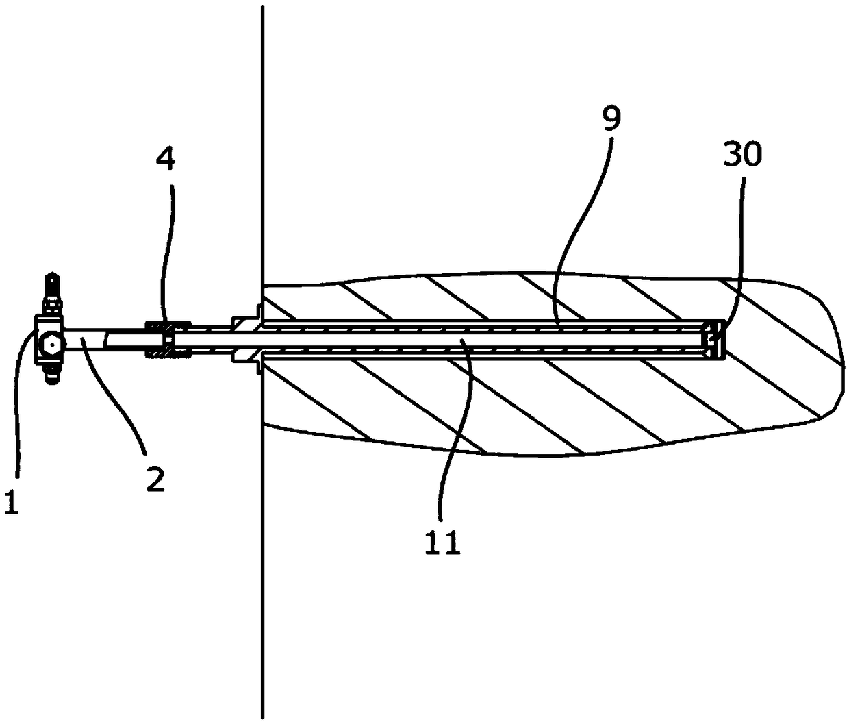
[0029] figure 1 An exemplary embodiment of an apparatus 1 for rock reinforcement, or sometimes referred to as rock bolting, is shown. The device 1 has been coupled to a rock bolt 11 via a mixer 2 and a connecting device 4 . figure 1 Also shown is a rock hole 9 in a mountain, wherein a rock bolt 11 has been placed in the rock hole 9 .

[0030] When the rock needs to be strengthened, the rock hole 9 is drilled in the rock. This is accomplished by using an electric drill or by using self-drilling bolts. figure 1 The rock bolt 9 in FIG. 1 shows a self-drilling bolt including a drill bit 30 . Self-drilling bolts are placed in rock holes, however and at the same time earth rock holes are formed by self...


PUM


Abstract

A method (100) and an apparatus (1) for rock reinforcement are described. The method (100) comprises the steps: to inject (101) a first component (A) and a second component (B) through a first channel(3) and a second channel (5) respectively into a rock hole (9), wherein the first component (A) and the second component (B) are adapted for rock reinforcement and to inject (103) a blocking agent (S) through a third channel (7) into at least said second channel (5), wherein said blocking agent (S) provides a barrier in at least said second channel (5).

Description

technical field [0001] This invention relates to the mining industry. In particular, the invention relates to methods and devices for rock reinforcement, eg in connection with tunneling. Background technique [0002] In conjunction with tunneling or in mines, cracks in rock formations often occur around cavities, eg in mountains, through which future tunnels will extend. The cracks shake the rocks in the mountain, which can lead to the possible collapse of multiple parts of the mountain. Therefore, actions to reduce the risk of collapse are required. These actions are often referred to as rock hardening. A common method used for rock reinforcement is rock bolting. Rock bolting means that the bolt suitable for rock bolting is fastened in the borehole by a molding agent. The layers of rock are bonded and held together in this way so that the risk of collapse is reduced. [0003] WO2012171056 describes a device for injecting resin in combination with rock bolts. The appa...

Claims


Application Information

Patent Timeline
IPC IPC(8): E21D20/02
CPCE21D20/028E21D20/02E21D20/025B01F35/145E21D21/0053
Inventor 维克托·伯格斯特
Owner EPIROC ROCK DRILLS AB
Why Eureka
Try Eureka