
Tearing, milling and fragmenting device for machining hard solids in kitchen waste
A technology of food waste and chemical equipment, which is applied in the direction of grain processing, etc., can solve the problems of broken bowls and glass pieces, food waste crushing, solid-liquid separation, etc., and achieve the effect of reducing processing resistance
- Summary
- Abstract
- Description
- Claims
- Application Information
AI Technical Summary
Problems solved by technology
Method used
Image

Examples
Embodiment 1
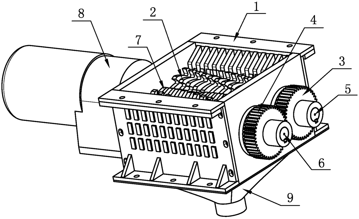
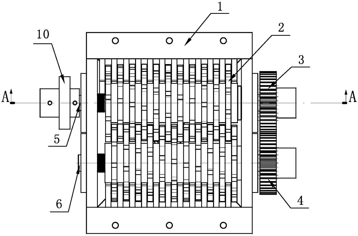
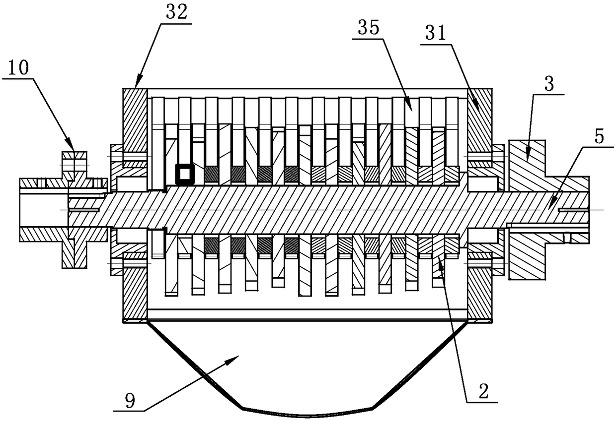
[0024] A hard solid object tearing and crushing device for processing food waste, such as Figure 1-Figure 6 As shown, it includes a shredding box body 1, a driving knife group 2, a driving wheel 3, a driven wheel 4, a driving shaft 5, a driven shaft 6, a driven knife group 7 and a shredding driving part 8, and the shredding box body 1. It includes a front side plate 31, a rear side plate 32, a left side plate 33, a right side plate 34, a left side sub knife plate 35 and a right side side knife plate 36. The front side plate 31 and the rear side plate 32 are arranged in parallel, and the left side The plate 33 and the right side plate 34 are arranged between the front side plate 31 and the rear side plate 32 respectively, and the four form a frame body with openings at both ends. The shaft installation hole system 37 and the driven shaft installation hole system 38 are provided with a left auxiliary knife plate 35 on the inner side of the left side plate 33, and a right side a...
PUM
 Abstract
Description
Claims
Application Information