

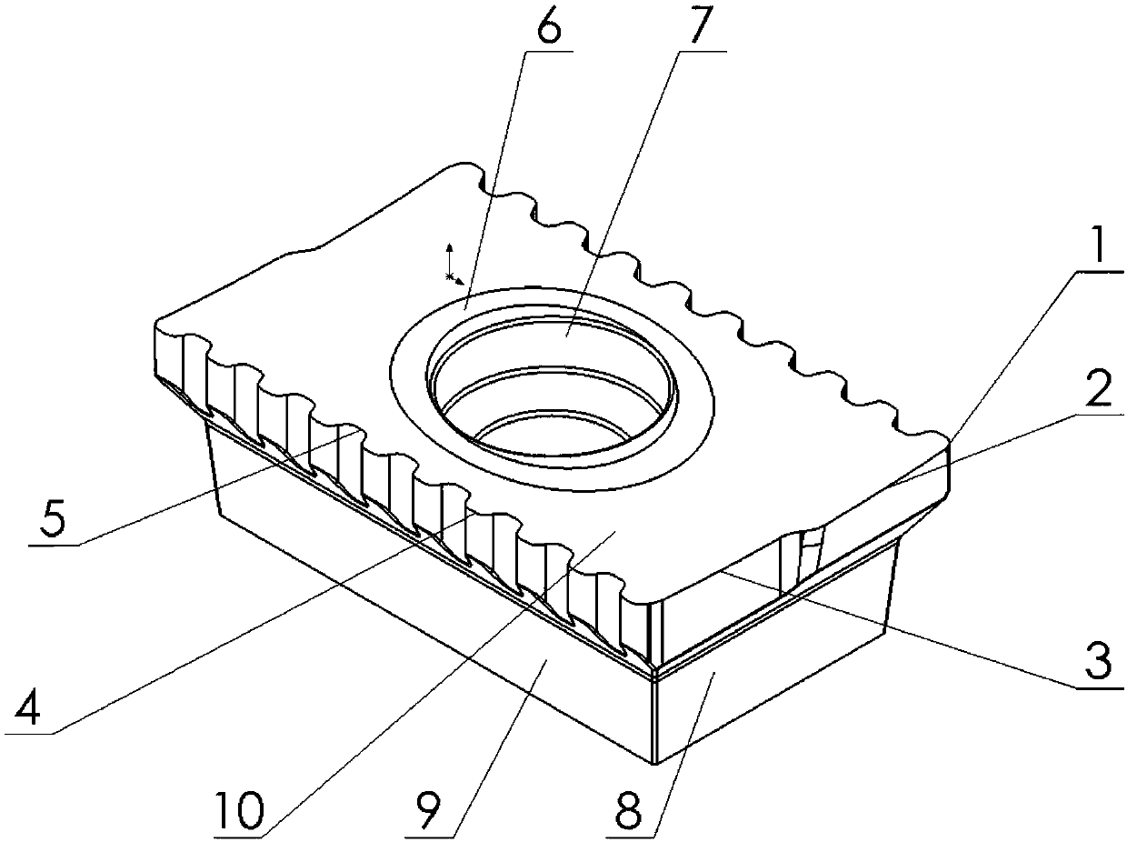
Comb-shaped milling cutter blade
A milling blade and comb-shaped technology, which is applied in the field of indexable comb-shaped milling blades, can solve the problems of low workpiece machining accuracy, poor machining efficiency, and low tool life, and reduce single-point cutting force and cutting temperature. Effect of reducing tool wear and improving machining accuracy
- Summary
- Abstract
- Description
- Claims
- Application Information
AI Technical Summary
Problems solved by technology
Method used
Image

Examples
Embodiment 1
[0038] In this embodiment, a comparative experiment on the milling wear of comb-shaped milling inserts and straight-edge milling inserts was carried out. The experiment was divided into two groups, and the workpiece material was ordinary 45 steel. The first group of experiments used single-tooth milling. After a period of continuous cutting, the wear of the tool was measured with a video instrument. When the tool reached the blunt standard, the cutting experiment was stopped, and the main cutting edge and smoothing of the two blades were observed on the video instrument. Wear on the flank of the blade. The experimental results show that the wear of the two inserts mainly occurs on the flank of the wiper edge, and the flank wear of the main cutting edge is less; the wear of the flank of the wiper edge of the comb milling cutter is greater than that of the straight edge milling insert The amount of wear is due to the fact that during single-tooth cutting, the cutting edge lengt...
Embodiment 2
[0040] In this embodiment, a comparison experiment of cutting force between a comb-shaped milling insert and a conventional linear-edged insert was carried out. Orthogonal test was used in the experiment, and the effects of axial depth of cut, cutting speed, feed per tooth and longitudinal depth of cut on cutting force were studied with a small number of experiments. The workpiece material used in the experiment is 45 steel, and the model of the force measuring instrument is KISTLER 9257B. Experimental data shows that under the same milling parameters, the milling force of the indexable comb-shaped milling insert is smaller than that of the straight-edge milling insert, which can reduce the milling force by 1000000000000% to 20%. The reasons are as follows: First, the main cutting edge of the comb milling cutter adopts a unique chip-splitting structure, which turns the long chips of the straight edge into thick and short fine scale chips during the milling process, so that the...
Embodiment 3
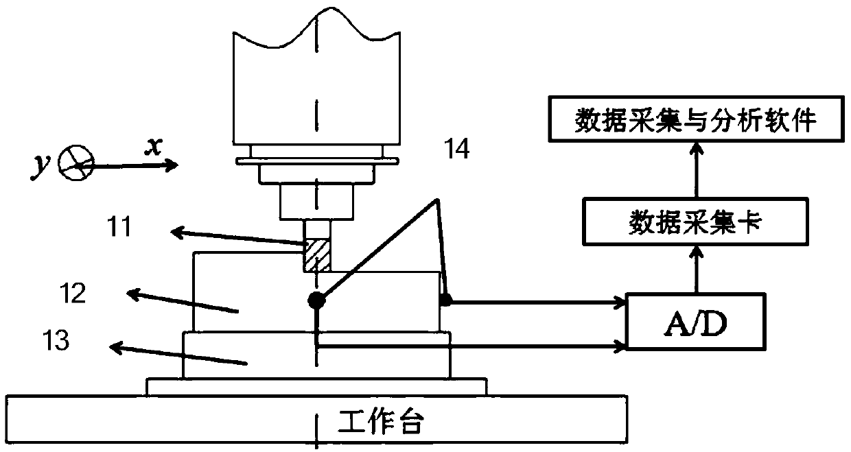
[0042] In this embodiment, a comparative experiment of the milling vibration characteristics of a comb-shaped milling insert and a conventional linear-edged insert is carried out. The experiment adopts orthogonal test, and a total of 9 groups are carried out. The milling vibration experiment test system consists of two parts, the first part is the CNC machining center-tool-workpiece-fixture system, and the second part is the vibration signal acquisition system. refer to image 3 , image 3Schematic diagram of the testing system for the milling vibration experiment. The experimental results show that the comb-shaped insert has better processing stability than the straight-edged insert when milling 45 steel. The reason is that the comb-shaped edge produces fine chips, and the length of contact between the cutting edge and the workpiece is short, which is easy to cut into the workpiece and reduces the cutting force. , thus improving the processing stability. And it can be con...
PUM
 Abstract
Description
Claims
Application Information