Traffic mechanical traction device

A mechanical traction and transportation technology, applied in the direction of traction connectors, transportation and packaging, vehicle parts, etc., can solve the problems of rear-end collision accidents of consigned vehicles, achieve the effect of convenient installation and reduce impact force

Inactive Publication Date: 2018-12-25
南昌保莱科技有限公司
View PDF6 Cites 4 Cited by
  • Summary
  • Abstract
  • Description
  • Claims
  • Application Information

AI Technical Summary

Problems solved by technology

[0005] Aiming at the deficiencies of the prior art, the present invention provides a traction device for traffic machinery, which solves the problem that the existing traction device for automobiles is often a steel wire rope with two traction hooks. Because the steel wire rope is relatively soft, the The faulty car is prone to rear-end accidents with the consigned car due to inertia

Method used


Image

  • Traffic mechanical traction device
  • Traffic mechanical traction device
  • Traffic mechanical traction device

Examples


Embodiment 1

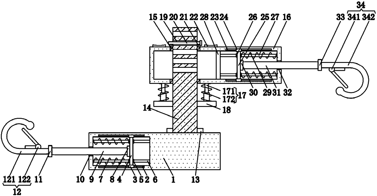
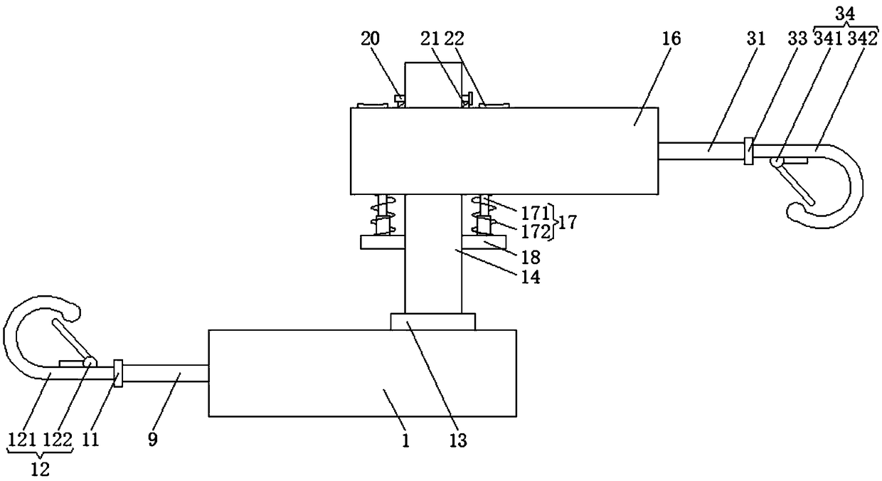
[0057] Example as Figure 1-3 As shown, the present invention provides a technical solution: a traction device for traffic machinery, comprising a first housing 1, the upper surface and the lower surface of the inner wall of the first housing 1 are provided with a first chute 2, and two second A first slide block 3 is slidably connected in each slide groove 2, the shape of the first slide groove 2 is T-shaped, and the shape of the first slide block 3 is T-shaped. By setting the first slide block 3 and the first slide groove 2 The shapes of the first chute 2 and the first slider 3 are both T-shaped, so that the first rotating shaft 9 drives the first connecting plate 4 to move left and right in the first housing 1 more flexibly, and the two The opposite surface of the first slider 3 is fixedly connected by the first connecting plate 4, two first sliding sleeves 5 are clamped on the side of the first connecting plate 4, and the second sliding sleeves 5 are sleeved inside the two...

Embodiment 2

[0060] Example two such as Figure 4 , 8 As shown, the steering mechanism 13 includes an outer rack ring 36, an intermediate gear 37, and an inner rack ring 38. The inner rack ring 38 is clamped on the right side of the upper surface of the first housing 1, and the outer side of the third rotating shaft 14 The outer rack ring 36 is sleeved, the intermediate gear 37 is located between the outer rack ring 36 and the inner rack ring 38, the intermediate gear 37 is meshed with the outer rack ring 36, and the intermediate gear 37 is meshed with the inner rack ring 38 .

[0061] The outer side of the outer rack ring 36 is provided with a blocking mechanism 39, the blocking mechanism 39 includes a third spring 40 and a raised frame 41, the outer side of the outer rack ring 36 is connected with a raised frame 41, and the third spring 40 is located on the raised frame 41 Inside, the two ends of the third spring 40 are respectively connected to the outer side of the outer rack ring 36...

Embodiment 3

[0066] Embodiment three such as Figure 5 , 8 As shown, the inner side of the inner rack ring 38 is provided with a blocking mechanism 39, the blocking mechanism 39 includes a third spring 40, a raised frame 41, the inner side of the inner rack ring 38 is connected with a raised frame 41, and the third spring 40 is located on the raised side. Inside the raised frame 41 , two ends of the third spring 40 are respectively connected to the inner side of the inner rack ring 38 and the inner side of the raised frame 41 .

[0067] There are two blocking mechanisms 39, and the angle between the two blocking mechanisms 39 is 150-180 degrees.

[0068] The raised frame 41 is made of flexible material.

[0069] When the third spring 40 is compressed to the limit, the distance from the inner side of the inner rack ring 38 to the top surface of the raised frame 41 is greater than the height of the teeth on the inner side of the inner rack ring 38 .

[0070] When the third spring 40 is co...


PUM


Abstract

A traffic mechanical traction device in accordance with the present invention, The first slider comprises a first casing, an upper surface and a lower surface of the inner wall of the first casing areprovided with a first sliding groove, two first sliding grooves are slidably connected with a first sliding block, and the opposite surfaces of the two first sliding blocks are fixedly connected witheach other through a first connecting plate, and two first sliding sleeves are clamped on the side surfaces of the first connecting plate. The utility model relates to a traffic mechanical traction device with an automatic adjustment function, through the first rotational shaft, First spring, steering mechanism, third axis of rotation, a fit between the second spring and the second rotational shaft, The traffic mechanical traction device not only prevents the rear-end collision between the faulty vehicle and the consignment vehicle due to inertia and other reasons, but also makes the consignment vehicle and the faulty vehicle have a certain buffer force, thereby reducing the impact force of the faulty vehicle on the consignment vehicle due to inertia or failure to brake in time, so that the faulty vehicle and the consignment vehicle can be well protected.

Description

technical field [0001] The invention relates to the technical field of traffic machinery, in particular to a traffic machinery traction device. Background technique [0002] The car tow hook is one of the auxiliary driving tools of the car. Its function is to connect the front car with the rear car, so that the front car can be towed away by the front car when the rear car fails. [0003] Sometimes a car breaks down while driving. At this time, it is necessary to use a traction device to pull the faulty car away. However, the existing traction device for automobiles is often a steel wire rope with two traction hooks. Because the steel wire rope is soft, In the process of consignment, the faulty vehicle is prone to a rear-end collision with the consignment vehicle due to inertia, so a traffic machinery traction device is urgently needed to solve the above problems. Contents of the invention [0004] (1) Solved technical problems [0005] Aiming at the deficiencies of the ...

Claims


Application Information

Patent Timeline
Patent Type & Authority Applications(China)
IPC IPC(8): B60D1/07B60D1/24B60D1/46B60D1/34
CPCB60D1/07B60D1/24B60D1/243B60D1/249B60D1/34B60D1/46
Inventor 不公告发明人
Owner 南昌保莱科技有限公司
Why Eureka
Try Eureka