A transport machinery traction device with adjustment function
A mechanical traction and transportation technology, applied in traction connectors, vehicle components, transportation and packaging, etc., can solve problems such as rear-end collision accidents of consigned vehicles, and achieve good protection and convenient installation
- Summary
- Abstract
- Description
- Claims
- Application Information
AI Technical Summary
Problems solved by technology
Method used
Image
Examples
Embodiment 1
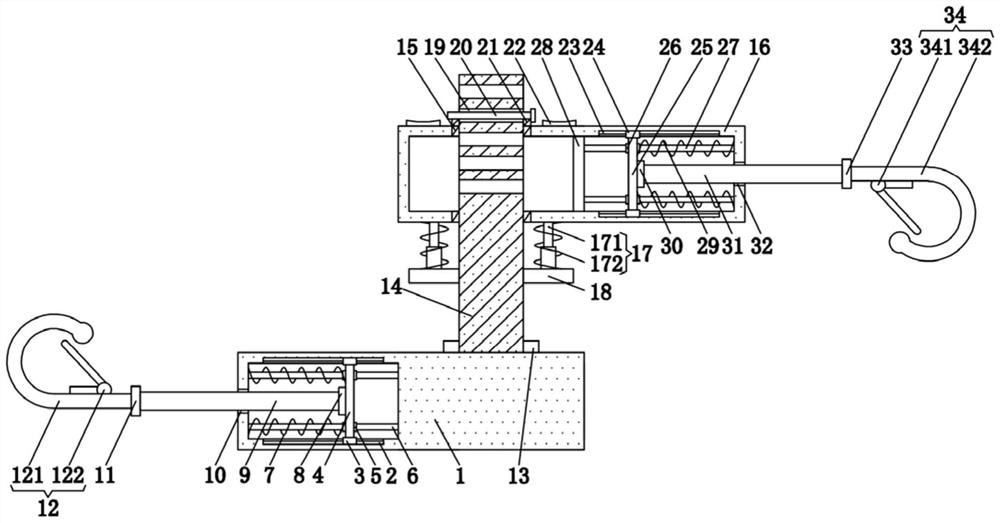
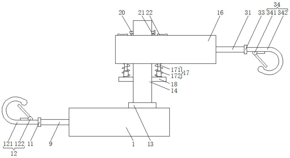
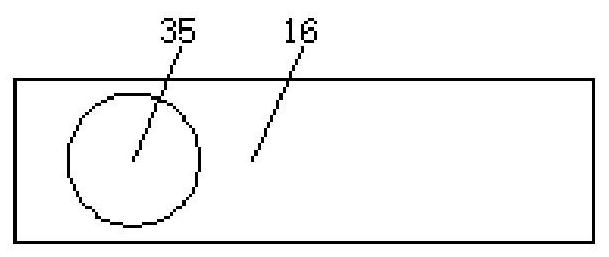
[0057] Example as Figure 1-3 As shown, the present invention provides a technical solution: a traffic machinery traction device with an adjustment function, comprising a first housing 1, the upper surface and the lower surface of the inner wall of the first housing 1 are provided with a first chute 2, And the first sliding block 3 is slidingly connected in the two first chute 2, the shape of the first chute 2 is T-shaped, the shape of the first sliding block 3 is T-shaped, by setting the first sliding block 3 and the second A chute 2, the shape of the first chute 2 and the first slider 3 is T-shaped, so that the first rotating shaft 9 drives the first connecting plate 4 to move left and right in the first housing 1 more smoothly. Flexible, and the opposite surfaces of the two first sliders 3 are fixedly connected by the first connecting plate 4, the side of the first connecting plate 4 is clamped with two first sliding sleeves 5, and the inside of the two first sliding sleeve...
Embodiment 2
[0060] Example two such as Figure 4 , 8 As shown, the steering mechanism 13 includes an outer rack ring 36, an intermediate gear 37, and an inner rack ring 38. The inner rack ring 38 is clamped on the right side of the upper surface of the first housing 1, and the outer side of the third rotating shaft 14 The outer rack ring 36 is sleeved, the intermediate gear 37 is located between the outer rack ring 36 and the inner rack ring 38, the intermediate gear 37 is meshed with the outer rack ring 36, and the intermediate gear 37 is meshed with the inner rack ring 38 .
[0061] The outer side of the outer rack ring 36 is provided with a blocking mechanism 39, the blocking mechanism 39 includes a third spring 40 and a raised frame 41, the outer side of the outer rack ring 36 is connected with a raised frame 41, and the third spring 40 is located on the raised frame 41 Inside, the two ends of the third spring 40 are respectively connected to the outer side of the outer rack ring 36...
Embodiment 3
[0066] Embodiment three such as Figure 5 , 8 As shown, the inner side of the inner rack ring 38 is provided with a blocking mechanism 39, the blocking mechanism 39 includes a third spring 40, a raised frame 41, the inner side of the inner rack ring 38 is connected with a raised frame 41, and the third spring 40 is located on the raised side. Inside the raised frame 41 , two ends of the third spring 40 are respectively connected to the inner side of the inner rack ring 38 and the inner side of the raised frame 41 .
[0067] There are two blocking mechanisms 39, and the angle between the two blocking mechanisms 39 is 150-180 degrees.
[0068] The raised frame 41 is made of flexible material.
[0069] When the third spring 40 is compressed to the limit, the distance from the inner side of the inner rack ring 38 to the top surface of the raised frame 41 is greater than the height of the teeth on the inner side of the inner rack ring 38 .
[0070] When the third spring 40 is co...
PUM
 Abstract
Description
Claims
Application Information
 - R&D
- Intellectual Property
- Life Sciences
- Materials
- Tech Scout
- Unparalleled Data Quality
- Higher Quality Content
- 60% Fewer Hallucinations
Browse by: Latest US Patents, China's latest patents, Technical Efficacy Thesaurus, Application Domain, Technology Topic, Popular Technical Reports.
© 2025 PatSnap. All rights reserved.Legal|Privacy policy|Modern Slavery Act Transparency Statement|Sitemap|About US| Contact US: help@patsnap.com


