
Evaporation plating device

A technology of evaporation and evaporation source, which is applied in vacuum evaporation plating, sputtering plating, ion implantation plating, etc., and can solve problems such as contamination in the chamber of the evaporation device

Active Publication Date: 2018-12-25
WUHAN CHINA STAR OPTOELECTRONICS SEMICON DISPLAY TECH CO LTD
View PDF5 Cites 2 Cited by
  • Summary
  • Abstract
  • Description
  • Claims
  • Application Information

AI Technical Summary

Problems solved by technology

[0003] However, in the evaporation process, due to the high temperature, the black impurities in the organic material are volatilized from the evaporation source equipment and attached to the chamber of the evaporation device, resulting in the contamination of the chamber of the evaporation device.

Method used


Image

  • Evaporation plating device
  • Evaporation plating device
  • Evaporation plating device

Examples


Embodiment Construction

[0032] The following will clearly and completely describe the technical solutions in the embodiments of the present invention with reference to the drawings in the embodiments of the present invention. Apparently, the described embodiments are only some of the embodiments of the present invention, but not all of them. Based on the embodiments of the present invention, all other embodiments obtained by those skilled in the art without creative efforts fall within the protection scope of the present invention.

[0033] In describing the present invention, it should be understood that the terms "center", "longitudinal", "transverse", "length", "width", "thickness", "upper", "lower", "front", " Orientation indicated by rear, left, right, vertical, horizontal, top, bottom, inside, outside, clockwise, counterclockwise, etc. The positional relationship is based on the orientation or positional relationship shown in the drawings, which is only for the convenience of describing the pr...


PUM


Abstract

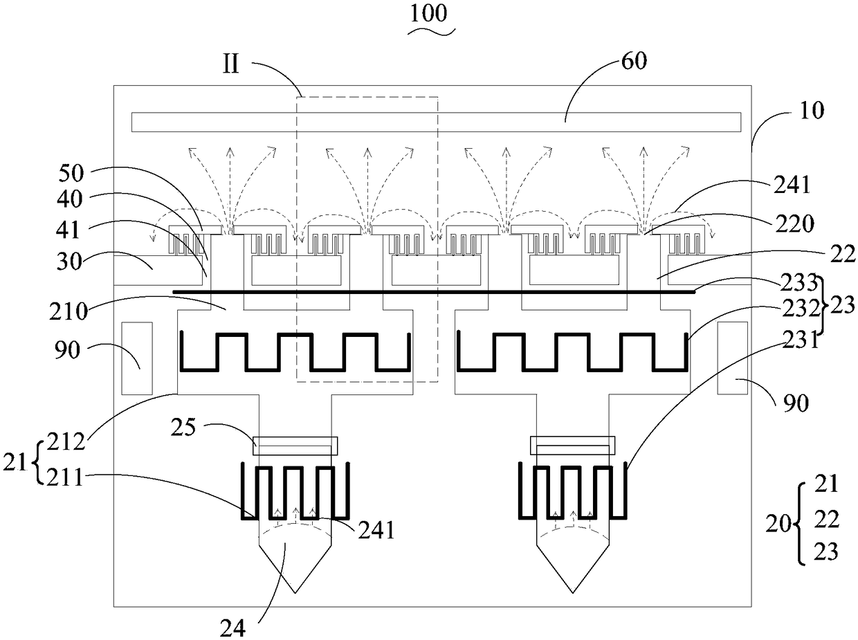
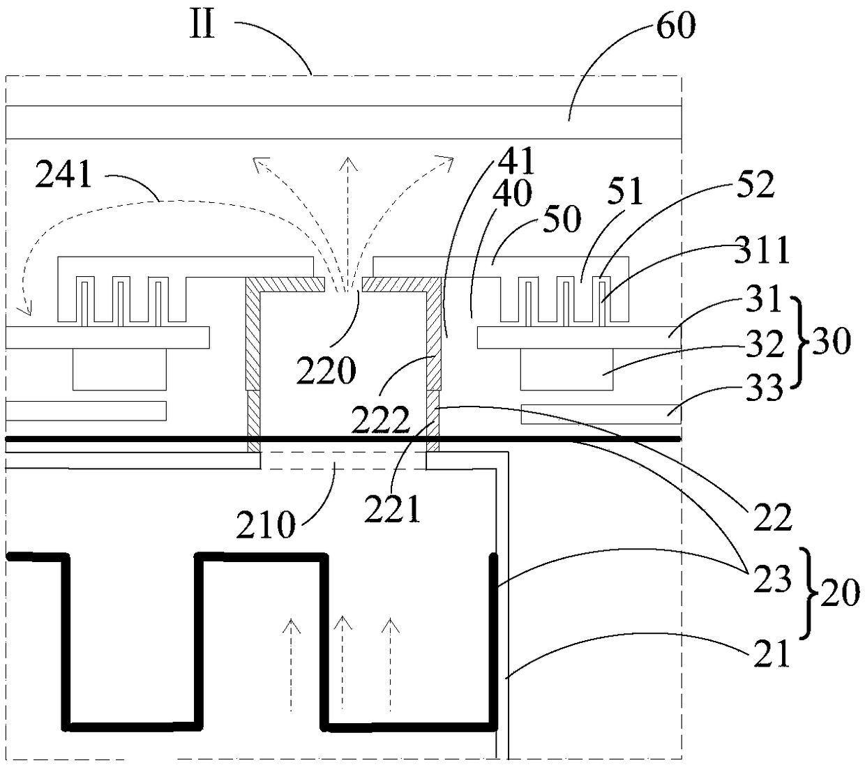
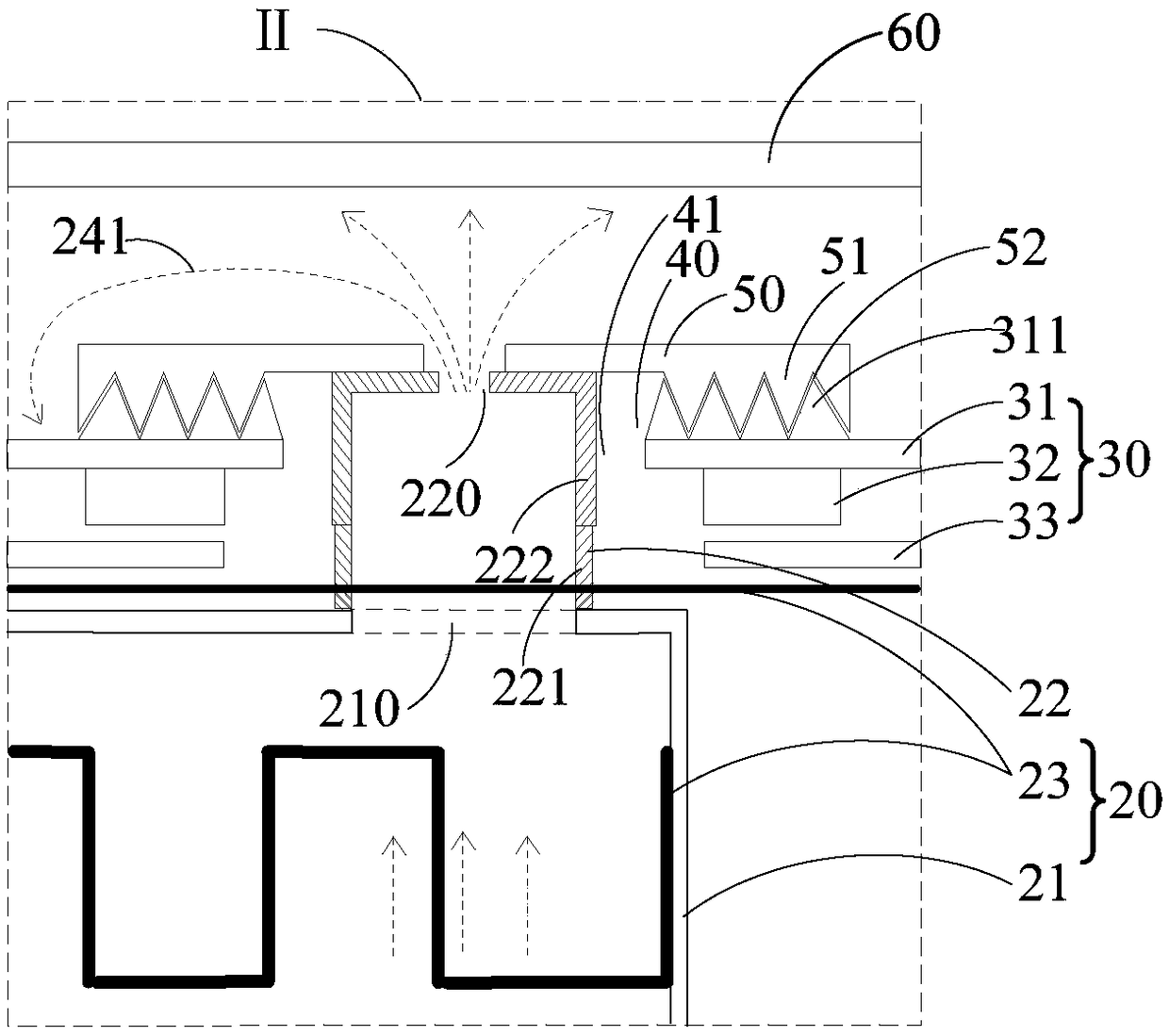
The invention discloses an evaporation plating device. The evaporation plating device comprises a shell, an evaporation plating source unit and an adjusting unit, wherein the evaporation plating source unit and the adjusting unit are positioned in the shell; the evaporation plating source unit comprises a crucible, a nozzle part and a heating part, wherein an evaporation plating material is accommodated in the crucible; an opening is formed in the crucible; the nozzle part is formed in the opening of the crucible; an open part used for enabling vapor of the evaporation plating material to be sprayed out is formed in the nozzle part; the heating part is arranged around the crucible and the nozzle part; the adjusting unit is arranged around the nozzle part; a protection structure is arrangedat the neighbouring part between the adjusting unit and the nozzle part; and the protection structure is used for stopping the vapor of the evaporation plating material from invading a gap in the neighbouring part between the adjusting unit and the nozzle part. The evaporation plating device disclosed by the embodiment of the invention has the advantages that the diffusion path of a pollution source can be prolonged by arranging the protection structure at the neighbouring part between the adjusting unit and the nozzle part, and the connection gaps between devices in the evaporation plating device can be narrowed to prevent pollution in a cavity of the evaporation plating device.

Description

technical field [0001] The invention relates to the field of display technology, in particular to an evaporation device. Background technique [0002] The main manufacturing process of organic EL (Electro Luminesence, electroluminescent) devices is generally manufactured by evaporation technology, and the specific operation of evaporation is to heat the evaporation material through a heater, so that the evaporation material is heated and evaporated on the surface of the substrate. membrane. Wherein, the EL device may include an OLED panel, etc., and the evaporation material may be an organic material. [0003] However, in the evaporation process, due to the high temperature, the black impurities in the organic material are volatilized from the evaporation source equipment and attached to the cavity of the evaporation device, resulting in contamination in the cavity of the evaporation device. [0004] Therefore, there are defects in the prior art, and improvement is badly n...

Claims


Application Information

Patent Timeline
Patent Type & Authority Applications(China)
IPC IPC(8): C23C14/24C23C14/56C23C14/12
CPCC23C14/12C23C14/24C23C14/564
Inventor 郑敏
Owner WUHAN CHINA STAR OPTOELECTRONICS SEMICON DISPLAY TECH CO LTD
Learn More