Liftable scaffolding device for interior decoration

A technology for lifting scaffolding and interior decoration, applied in the directions of construction, housing structure support, housing structure support, etc., can solve the problem of scaffolding being unusable without electricity, and achieve the effect of novel design and convenient use.

Active Publication Date: 2020-10-02
天威虎建设股份有限公司
View PDF3 Cites 0 Cited by
  • Summary
  • Abstract
  • Description
  • Claims
  • Application Information

AI Technical Summary

Problems solved by technology

[0003] The existing new type of scaffolding adopts electric drive to realize lifting. It does not take up space when it is put away, it is convenient to transport, and it does not need to be built on site. It is easy to move and is widely used. When it is higher, if the power is suddenly cut off, it will be troublesome for the staff to come down, and there are certain limitations

Method used


Image

  • Liftable scaffolding device for interior decoration
  • Liftable scaffolding device for interior decoration
  • Liftable scaffolding device for interior decoration

Examples


Embodiment 1

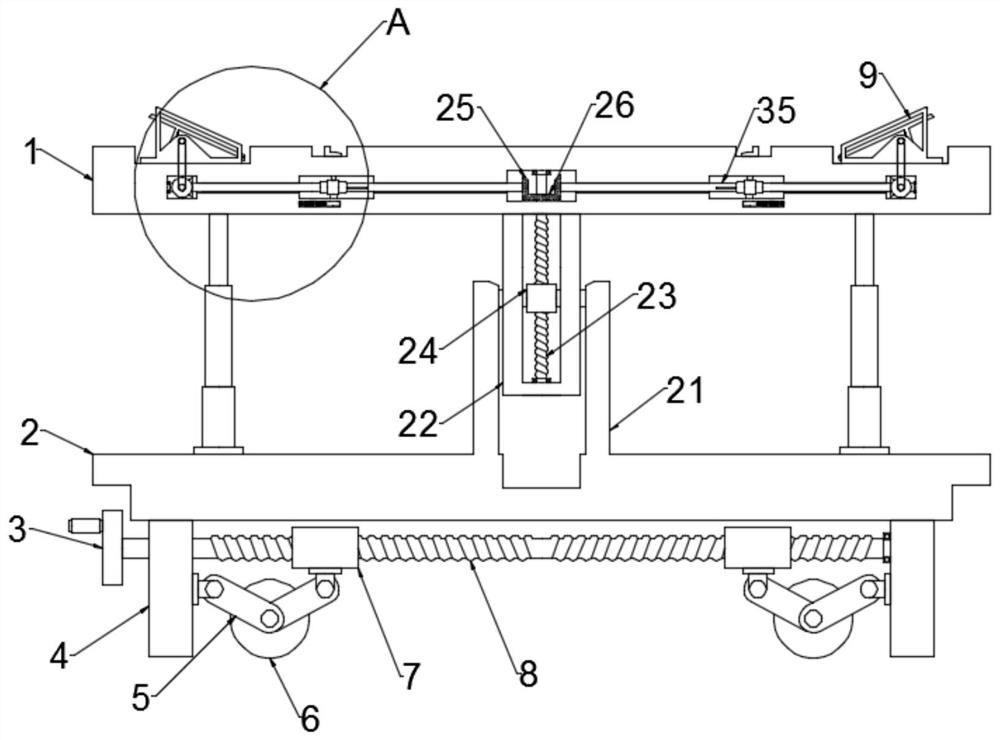
[0023] see Figure 1~5 , in an embodiment of the present invention, a liftable scaffolding device for interior decoration, including a support plate 1, a bottom plate 2 and a movable connection assembly; the support plate 1 is connected to the bottom plate 2 through symmetrically arranged multi-stage telescopic rods, A movable connection assembly is arranged between the multi-stage telescopic rods, and the upper and lower ends of the movable connection assembly are respectively fixed to the support plate 1 and the bottom plate 2. Preferably, the movable connection assembly includes a receiving cylinder 22 fixed on the lower end of the support plate 1, symmetrical The splint 21 fixed on the bottom plate 2, the receiving cylinder 22 is arranged between the two splints 21, and the splint 21 is fixedly connected with the second threaded sleeve 24 arranged in the receiving cylinder 22 through the installation block, the second threaded sleeve 24 Threaded on the threaded rod 23, whe...

Embodiment 2

[0029] In order to facilitate the movement of the device without affecting its stability during use, this embodiment optimizes it. Specifically, legs 4 are symmetrically installed on the lower end of the bottom plate 2, and two-way Threaded rod 8, one end of the two-way threaded rod 8 rotates on the leg 4, the other end of which runs through the other leg 4 and is fixedly connected to the turntable 3, symmetrically arranged on the two-way threaded rod 8 inside the two legs 4 There is a first threaded sleeve 7, a roller 6 is arranged below the first threaded sleeve 7, and connecting rods 5 are symmetrically installed on the rotating shaft of the rollers 6, one connecting rod 5 is hinged with the supporting leg 4, and the other connecting rod 5 is hinged on the The lower end of the first threaded sleeve 7 drives the two-way threaded rod 8 to rotate through the turntable 3. When the two-way threaded rod 8 rotates, it drives the two first threaded sleeves 7 to move toward each othe...


PUM


Abstract

The invention discloses a lifting scaffold device for indoor decoration. The device comprises a supporting plate, a bottom plate and a movable connection component; the supporting plate and the movable connection component are connected with the bottom plate, the upper end and the lower end of the movable connection component are fixed to the supporting plate and the bottom plate respectively, a bevel gear B is fixedly connected to the upper end of a threaded rod, and the two sides of the upper end of the bevel gear B are symmetrically provided with bevel gears A fixed to adjusting mechanisms;each adjusting mechanism comprises a pedal mechanism and a gear transmission assembly, and the pedal mechanisms are connected with the bevel gears A through the gear transmission assemblies. The device is novel in design, the pedal mechanisms drive bevel gears C to rotate, when the bevel gears C rotate, first rotating rods are driven by bevel gears D meshed with the bevel gears C to rotate, and the first rotating rods drive the bevel gears B to rotate through second rotating rods, so that the threaded rod is driven to rotate, and a supporting rod ascends and descends. The two pedal mechanismscontrol the threaded rod to rotate forward and reversely, and then the supporting rod ascends and descends.

Description

technical field [0001] The invention relates to the technical field of interior decoration, in particular to a liftable scaffolding device for interior decoration. Background technique [0002] Scaffolding is a working platform set up to ensure the smooth progress of various construction processes. According to the erection position, it can be divided into external scaffolding and internal scaffolding; according to different materials, it can be divided into wooden scaffolding, bamboo scaffolding and steel pipe scaffolding; according to the structure form, it can be divided into vertical pole scaffolding, bridge scaffolding, portal scaffolding, suspension scaffolding Hanging scaffolding, picking scaffolding, climbing scaffolding. With the emergence of a large number of modern large-scale building systems in our country, the fastener-type steel pipe scaffolding can no longer meet the needs of building construction development. It is urgent to vigorously develop and promote t...

Claims


Application Information

Patent Timeline
Patent Type & Authority Patents(China)
IPC IPC(8): E04G1/15E04G1/22E04G1/24
CPCE04G1/15E04G1/22E04G1/24E04G2001/242
Inventor 吴天威刘振功
Owner 天威虎建设股份有限公司
Why Eureka
Try Eureka