Borderless Wiring Appliances

A frame wiring and appliance technology, applied in the field of frameless wiring appliances, can solve problems such as deformation of the mounting frame and affect the overall appearance of the wiring appliance, and achieve the effect of avoiding the left and right sides from warping

Active Publication Date: 2020-08-04
PANASONIC INFORMATION INSTR SHANGHAI
View PDF8 Cites 0 Cited by
  • Summary
  • Abstract
  • Description
  • Claims
  • Application Information

AI Technical Summary

Problems solved by technology

[0003] At present, the installation frames of most wiring appliances are installed and fixed on the dark box in the wall by screws. When the screws are tightened on the light box, the installation frame will be deformed due to stress, which is manifested in the left and right sides of the installation frame. The direction of the user is tilted, thereby affecting the overall appearance of the wiring appliance

Method used


Image

  • Borderless Wiring Appliances
  • Borderless Wiring Appliances
  • Borderless Wiring Appliances

Examples


no. 1 approach

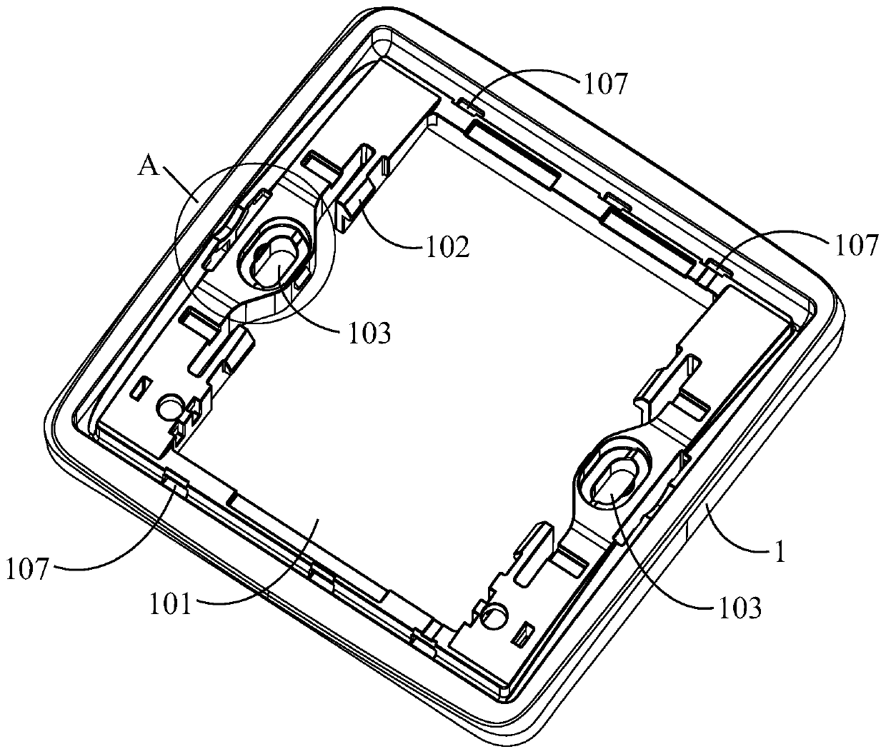
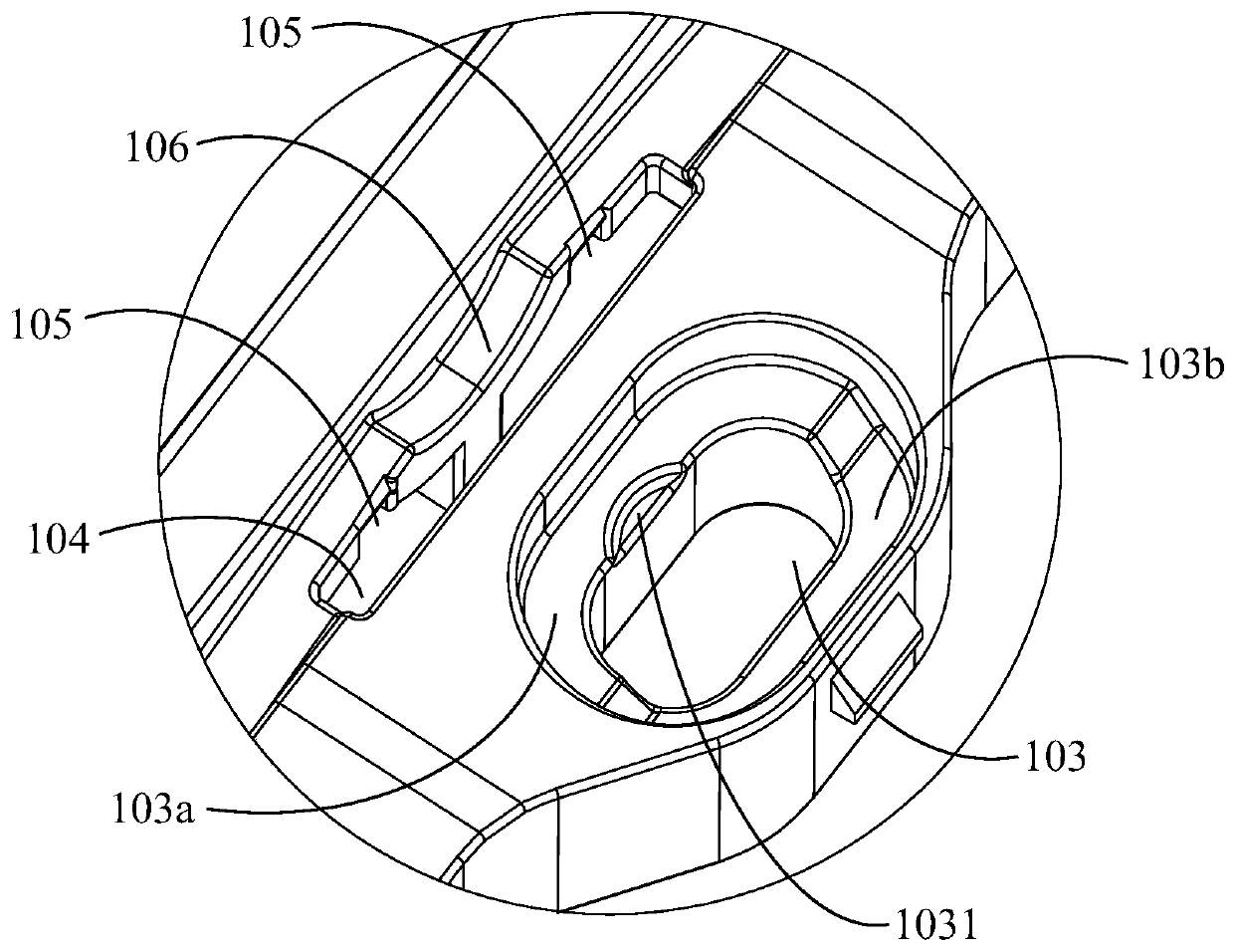
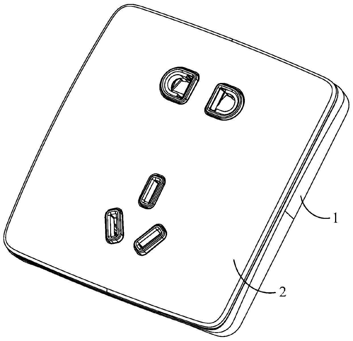
[0052] image 3 The three-dimensional structure of the five-hole socket of this embodiment is shown, Figure 4 The back structure of the decorative panel 2 of the five-hole socket of this embodiment is shown, Figure 5 show Figure 4 Partial enlarged view of part B in the middle, Figure 3 ~ Figure 5 to combine Figure 1 ~ Figure 2 It is used to illustrate the installation and cooperation structure of the decorative panel 2 and the installation frame 1 of the five-hole socket.

[0053] see figure 1 , Figure 4 and combine image 3 , the upper and lower sides of the mounting frame 1 are provided with first slots 107 for the upper and lower sides of the decorative panel 2 to engage with the mounting frame 1, correspondingly, as Figure 4 As shown, the upper and lower sides of the back of the decorative panel 2 are provided with a first hook 201 that can be engaged with the first slot 107, and the first hook 201 has a first protrusion that can be hooked into the first slot...

no. 2 approach

[0062] In this embodiment, the same reference numerals as in the first embodiment denote the same component names. Hereinafter, the similarities between this embodiment and the first embodiment will be briefly described, and the differences between the two will be mainly described.

[0063] Figure 7 The three-dimensional structure of the emergency button switch of this embodiment is shown, Figure 8 The rear structure of the decorative panel 2 of the emergency push button switch of this embodiment is shown.

[0064] see figure 1 , Figure 8 and combine Figure 7 , in this embodiment, the installation and cooperation relationship between the decorative panel 2 of the emergency button switch and the mounting frame 1 is the same as that of the first embodiment, both through the engagement of the first card slot 107 and the first hook 201 and the second card slot 105 and the second hook 202 to realize the assembly of the two.

[0065] Different from the first embodiment, th...

no. 3 approach

[0068] Figure 9 The three-dimensional structure of the one-position switch of this embodiment is shown, Figure 10 The back structure of the operation panel 5 of the one-position switch of this embodiment is shown, Figure 11 The specific structure of the engaging part on the operation panel 5 of this embodiment is shown, Figure 12 shows the internal structure of the one-position switch of this embodiment, Figure 13 The assembly structure of the operation panel 5 and the internal operation handle 6 of this embodiment is shown, Figure 14 An enlarged structure of the assembly portion of the operation panel 5 and the inner operation handle 6 is shown.

[0069] see Figure 10 , Figure 11 , Figure 12 and combine Figure 9 In this embodiment, the electrical function module of the one-position switch is provided with an internal operation handle 6 for opening and closing the one-position switch, and the operation panel 5 is realized by being engaged with the internal ope...


PUM


Abstract

The invention discloses a borderless wiring appliance. The borderless wiring appliance is connected to a cassette arranged in a wall by screws. The borderless wiring appliance includes a mounting frame mounted in the cassette. The left and right sides of the mounting frame and the left and right sides of the cassette are provided with screw holes for the screws to pass through. The screws pass through the screw holes of the mounting frame and the screw holes of the cassette in order so as to fix the mounting frame to the cassette. The center line of the screw holes of the mounting frame is located at one side, being far from the center of the mounting frame, of the center line of the screw holes of the cassette. The borderless wiring appliance of the invention can be used to prevent the left and right sides of the mounting frame from wrapping up.

Description

technical field [0001] The invention relates to the field of wiring appliances, in particular to a frameless wiring appliance. Background technique [0002] Wiring appliances include switches, sockets, etc., which are connected in the circuit and are used to realize the on-off of the control circuit and provide power supply for external plug-in components. For the aesthetics of the wiring appliances, borderless wiring appliances emerge in endlessly. The frameless wiring appliances are connected to the dark box installed in the wall, which includes a mounting frame mounted on the dark box and a panel assembly that covers the mounting frame. The panel The assembly is capable of covering the internal parts of the wiring fixture, ie all parts located between the panel assembly and the wall. [0003] At present, the installation frames of most wiring appliances are installed and fixed on the dark box in the wall by screws. When the screws are tightened on the light box, the inst...

Claims


Application Information

Patent Timeline
Patent Type & Authority Patents(China)
IPC IPC(8): H01R13/506H01R13/627
CPCH01R13/506H01R13/6271
Inventor 朱佳骐
Owner PANASONIC INFORMATION INSTR SHANGHAI
Why Eureka
Try Eureka