

Optical adhesive layer, manufacturing method of optical adhesive layer, optical film with adhesive layer, and image display device
An adhesive layer and adhesive technology, which is applied in the field of optical films, can solve the problems that the stress relaxation properties of the adhesive layer become smaller and smaller (narrowing, light leakage, etc.) bubble effect
- Summary
- Abstract
- Description
- Claims
- Application Information
AI Technical Summary
Problems solved by technology
Method used
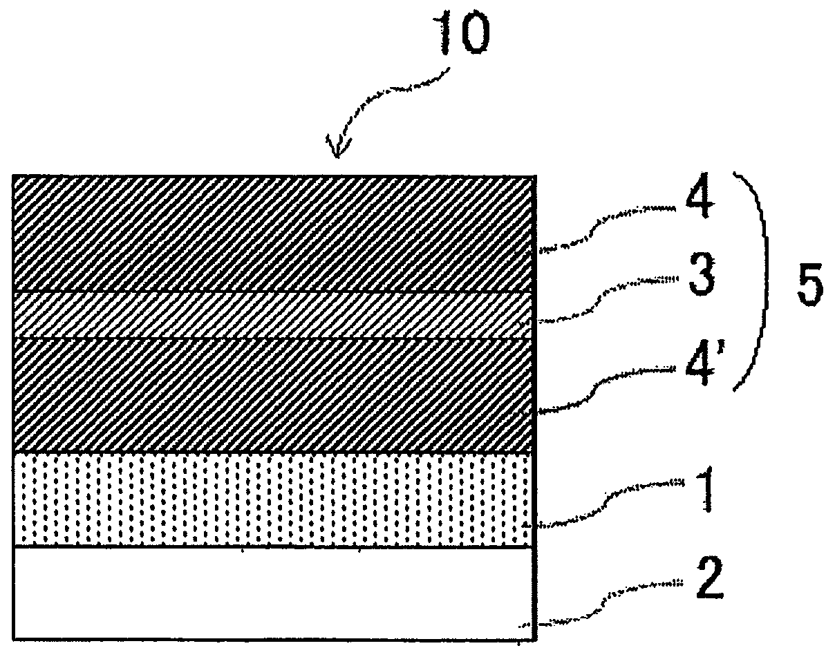
Image

Examples
Embodiment 1
[0147] (Preparation of (meth)acrylic polymer (A1))
[0148] A monomer mixture containing 95 parts of butyl acrylate and 5 parts of 4-hydroxybutyl acrylate was added to a 4-necked flask equipped with a stirring blade, a thermometer, a nitrogen gas introduction tube, and a condenser. Further, 0.1 part of 2,2'-azobisisobutyronitrile as a polymerization initiator was added to 100 parts of the above-mentioned monomer mixture (solid content), together with 85 parts of ethyl acetate and 15 parts of toluene, and introduced while stirring slowly. After replacing nitrogen with nitrogen, the liquid temperature in the flask was kept at around 55°C, and polymerization was carried out for 30 minutes to prepare a (meth)acrylic polymer with a weight average molecular weight (Mw) of 1.8 million and Mw / Mn=1.92 Solution of (A1).
[0149] (Preparation of Adhesive Composition)
[0150] With respect to 100 parts of solid content of the solution of the above-mentioned (meth)acrylic polymer (A1) ob...
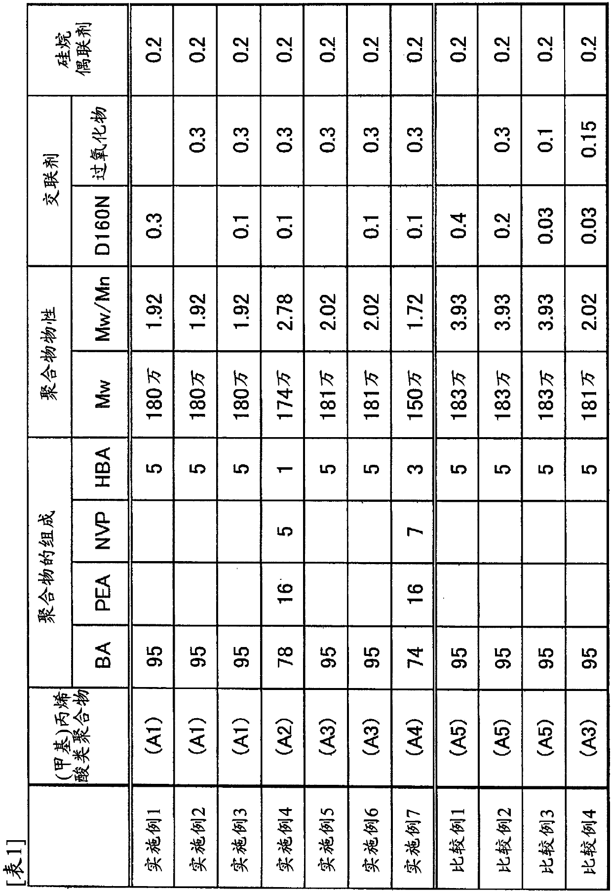
Embodiment 2~7、 and comparative example 1~4
[0163] In Examples 2 to 7 and Comparative Examples 1 to 4, the production methods of the above-mentioned (meth)acrylic polymers (A2) to (A5) were changed in the same manner as in Example 1, and changed as shown in Table 1. The types of monomers, their usage ratios, and the control of production conditions, prepared (meth)acrylic polymers with the polymer properties (weight-average molecular weight (Mw), polydispersity coefficient (Mw / Mn)) shown in Table 1. Solutions of (A2) to (A5).
[0164] In addition, except that the type or amount of the crosslinking agent was changed as shown in Table 1 with respect to each obtained (meth)acrylic polymer solution, an acrylic adhesive set was prepared in the same manner as in Example 1. solution of substances. Moreover, the polarizing film with an adhesive layer was produced similarly to Example 1 using the solution of the said acrylic adhesive composition.
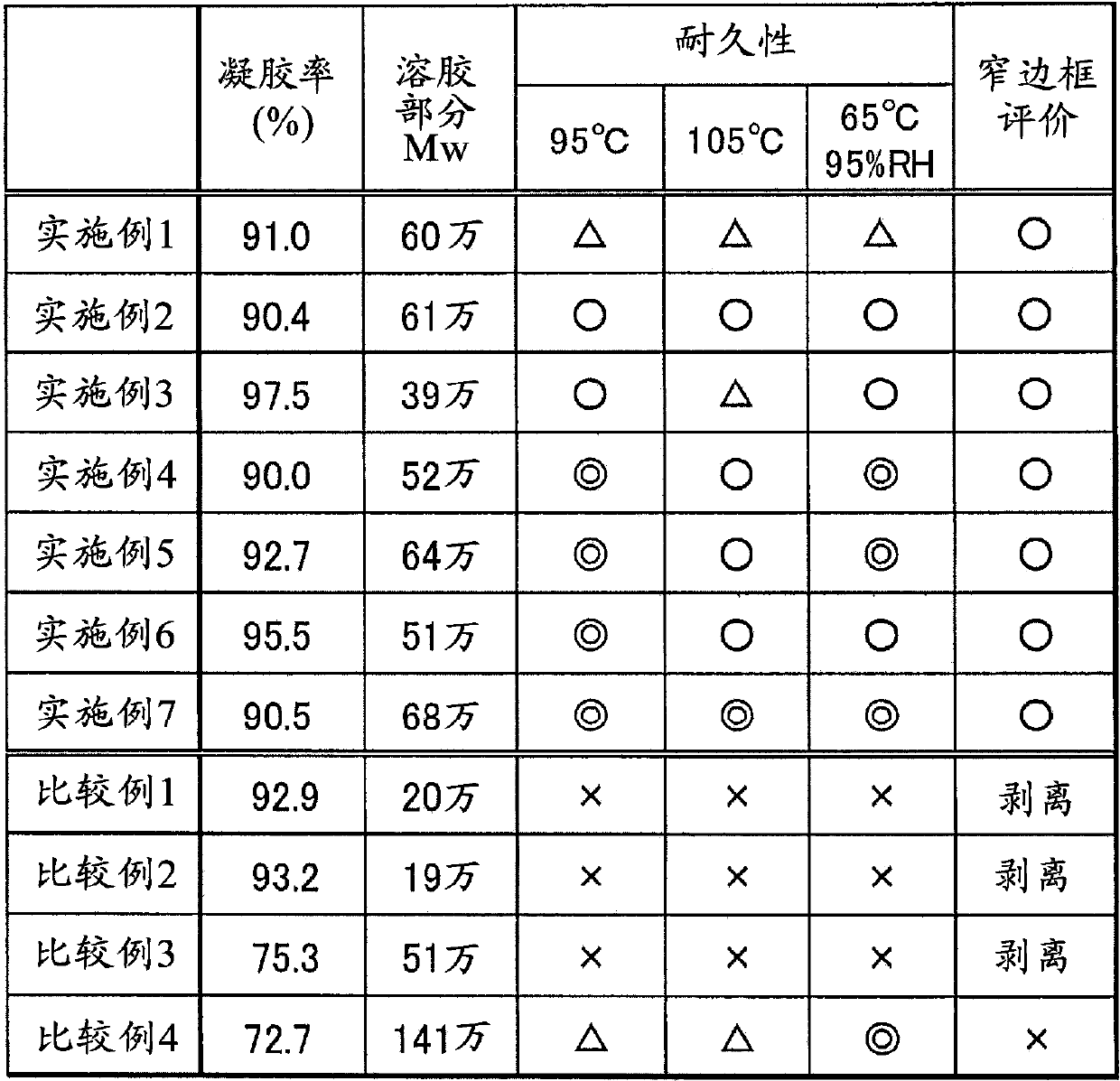
[0165] The following evaluations were performed about the polarizing film with ...
PUM
| Property | Measurement | Unit |
|---|---|---|
| thickness | aaaaa | aaaaa |
| size | aaaaa | aaaaa |
| gel rate | aaaaa | aaaaa |
Abstract
Description
Claims
Application Information