A power input filter protection circuit

A technology for power input and circuit protection, applied in emergency protection circuit devices, circuit devices, emergency protection devices with automatic disconnection, etc. Protect safety and solve the effect of easy fuse

Inactive Publication Date: 2018-12-25
北京乾中源科技有限公司
View PDF1 Cites 2 Cited by
  • Summary
  • Abstract
  • Description
  • Claims
  • Application Information

AI Technical Summary

Problems solved by technology

[0004] Once the existing power supply protection circuit is turned on, the high current will easily blow the fuse and cause the power supply to fail
And the fuse must be replaced after blown, which is inconvenient to maintain

Method used


Image

  • A power input filter protection circuit

Examples


specific Embodiment

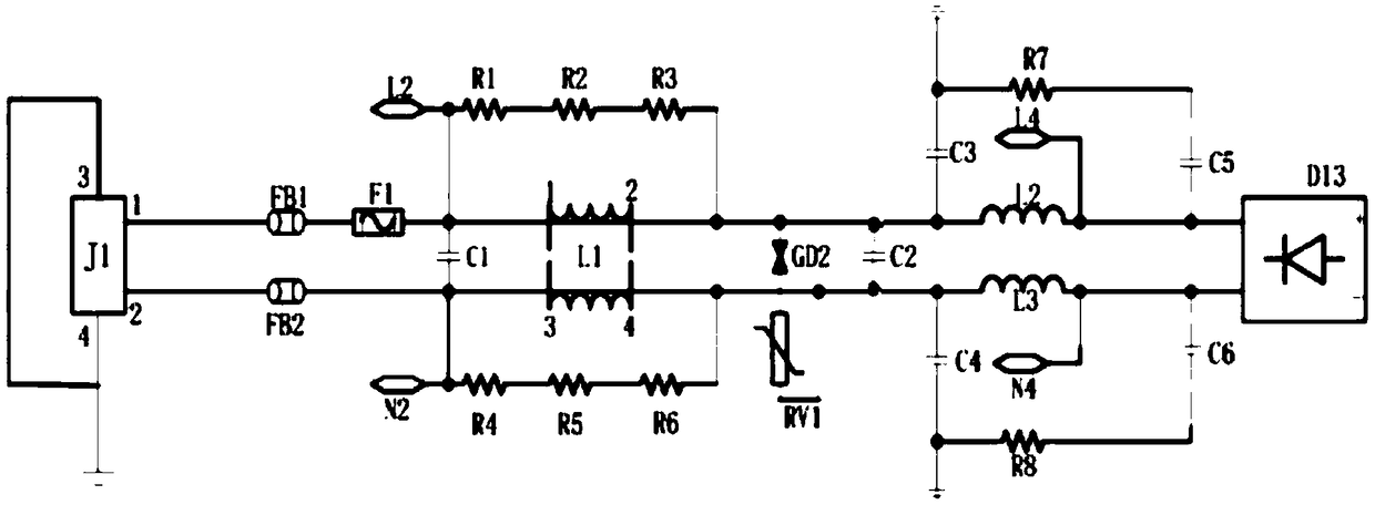
[0034] Specific examples, such as figure 1 Shown:

[0035] In order to make the purpose, technical solution and advantages of the present invention clearer, the magnetic ballast circuit of the present invention will be further described in detail below through the embodiments and with reference to the accompanying drawings. It should be understood that the specific embodiments described here are only used to explain the present invention, not to limit the present invention.

[0036] It should be noted that when an element is considered to be "connected" to another element, it may be directly connected to the other element or there may be intervening elements at the same time. In contrast, when an element is referred to as being "directly" connected to another element, there are no intervening elements present.

[0037] An embodiment of the present application provides a filter protection circuit for power supply. The circuit adopts a self-recovery fuse. When the overcurrent ...


PUM


Abstract

The invention discloses a power input filter protection circuit, comprising a power input connector, wherein the power input connector is connected with a filter circuit, a safety element is seriallyconnected on the fire line of the power input connector, the filter circuit is connected with a protection circuit, and the filter circuit and the protection circuit are respectively connected with arectifier bridge. The fuse element is self-recovery fuse; when the overcurrent and overheat faults of the circuit are eliminated, the self-recovery fuse will be automatically restored to a low resistance state without replacement, which is convenient to use and can protect the safety of the power supply system. Circuit elements are all patch elements, which have the advantages of small size and low cost.

Description

technical field [0001] The invention relates to a power supply system, in particular to a power supply input filter protection circuit. Background technique [0002] Compared with traditional power systems, military power systems have higher requirements for safety performance. The safety of the power system affects the realization of the stand-alone function at least, and affects the safety of the whole system at the most. In order to meet the special requirements of military power supplies, it is necessary to connect the power supply with an external input filter or use external discrete components to form a filter protection circuit to protect the power supply, so as to ensure that it does not interfere with or be interfered by other equipment, so as to ensure the realization of the functional performance of the whole machine. [0003] In the process of the prior art, it is found that at least the following problems exist: [0004] Once the existing power supply protect...

Claims


Application Information

Patent Timeline
Patent Type & Authority Applications(China)
IPC IPC(8): H02H3/06H02H7/125
CPCH02H7/125H02H3/066
Inventor 吴开波
Owner 北京乾中源科技有限公司
Why Eureka
Try Eureka