A styling device for a wig

A styling device and wig technology, applied in wigs, applications, clothing, etc., can solve the problems of large power consumption, water and protein reduction, resource waste, etc.

Inactive Publication Date: 2019-01-01
朱文统
View PDF0 Cites 2 Cited by
  • Summary
  • Abstract
  • Description
  • Claims
  • Application Information

AI Technical Summary

Problems solved by technology

With the changing of people's aesthetics, curly hair is becoming more and more popular in China. In the process of producing curly hair, it is necessary to curl the semi-finished wig. In the process of rolling, the traditional craft is to curl the semi-finished wig on the Then wrap a layer of fixed film on the outside, put it into an electric oven for electric baking, and the electric baking time is 60 to 90 minutes. During this process, the power consumption is relatively large, resulting in a large waste of resources. The enterprise has brought economic burden, moreover, when the existing oven is carrying out stereotyping to the wig, the temperature is higher, will certainly cause the moisture and the protein in the wig to reduce, cause damage to the wig easily, so design a kind of use hot steam to carry out the wig The stereotyped equipment is very necessary

Method used


Image

  • A styling device for a wig
  • A styling device for a wig

Examples


Embodiment 1

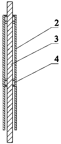
[0026] A styling device for wigs such as figure 1 As shown, it includes a base 1, a humidifying rack installed on the top of the base 1, and a humidifying mechanism installed on the humidifying rack, such as figure 2 As shown, the humidifying rack includes an outer sleeve 2 and a main shaft 3. The main shaft 3 is installed inside the outer sleeve 2 and the central axes of the two coincide. The outer sleeve 2 and the main shaft 3 are rotationally connected by a bearing I4. The bottom of the sleeve 2 is welded on the top of the base 1, and the top of the outer sleeve 2 is equipped with a mold ball 5 for placing a wig. The electric heating wire 6 is evenly wound in the mold ball 5, and the bottom end of the main shaft 3 is connected from the outer sleeve 2. After the inside of the main shaft 3 passes through the inner cavity of the base 1, it is connected to the motor 7, and the top of the main shaft 3 passes through the inside of the outer sleeve 2 and has a protruding end. The...

Embodiment 2

[0032] A styling device for wigs, comprising a base 1, a humidifying frame mounted on the top of the base 1, and a humidifying mechanism mounted on the humidifying frame, the humidifying frame includes an outer sleeve 2 and a main shaft 3, and the main shaft 3 is worn outside The inside of the sleeve 2 and the central axes of the two are coincident, the outer sleeve 2 and the main shaft 3 are rotationally connected by the bearing I4, the bottom of the outer sleeve 2 is welded to the top of the base 1, and the top of the outer sleeve 2 is installed with a Place the mold ball 5 of the wig, and the electric heating wire 6 is evenly wound in the mold ball 5. The bottom end of the main shaft 3 passes through the inside of the outer sleeve 2 and is connected with the motor 7 arranged in the inner cavity of the base 1. The top end passes through the inside of the outer sleeve 2 and has a protruding end. A driven wheel I8 is installed on the outside of the protruding end. The driven wh...


PUM


Abstract

The invention provides a styling device for a wig. The wig placed on the mold ball is uniformly and low-temperature heated by an electric heating wire to achieve preliminary setting, the spindle is then driven to rotate by a motor, the spindle drives the lead screw in the humidifying mechanism to rotate in the bearing II through the belt, the humidifying nozzle mounted on the screw reciprocates inthe vertical direction, so that the wig placed on the mold ball is sprayed and heated. In order to achieve the best heating effect, the humidifying mechanism can be provided with a plurality of groups, and a plurality of humidifying mechanisms can simultaneously work to heat the wig at 360 DEG without dead angle. The invention combines the transmission electric heating and the hot steam heating to ensure that there is sufficient moisture in the wig and prevent damage to the wig under the premise that the shaping of the wig can be satisfied.

Description

technical field [0001] The invention belongs to the technical field of wig styling, and in particular relates to a wig styling device. Background technique [0002] Nowadays, wigs worn in society are divided into wigs for performing arts and wigs for changing hairstyles in daily life. , dyeing hair, especially colored hair, has become a consumer fashion; demand creates the market, and a large number of factories produce fashionable wigs. In the past, wigs were generally straight hair, but in recent years, wigs appearing on the market have various appearances and shapes Mainly divided into long hair, medium long hair and short hair. With the changing of people's aesthetics, curly hair is becoming more and more popular in China. In the process of producing curly hair, it is necessary to curl the semi-finished wig. In the process of rolling, the traditional craft is to curl the semi-finished wig on the Then wrap a layer of fixed film on the outside, put it into an electric ov...

Claims


Application Information

Patent Timeline
Patent Type & Authority Applications(China)
IPC IPC(8): A41G3/00
CPCA41G3/0075
Inventor 朱文统
Owner 朱文统
Why Eureka
Try Eureka