
High-rise building fire-fighting rescue system

A high-rise building and firefighting technology, applied in building rescue, life-saving equipment and other directions, can solve the problems of slow rescue, no large-scale use, and high cost, and achieve the effect of fast installation speed, easy and fast rescue, and low cost.

Active Publication Date: 2019-01-01
辛现伟
View PDF13 Cites 4 Cited by
  • Summary
  • Abstract
  • Description
  • Claims
  • Application Information

AI Technical Summary

Problems solved by technology

Disadvantages: large building changes, high cost, no smoke and heat protection, difficult maintenance, or users not only need to overcome psychological fear, but also undergo special training, and have strict requirements for escape posture and arm strength
Not yet equipped on a large scale
Existing building rescue equipment, each building needs to be equipped with one or more sets of rescue systems, and the country needs to be equipped with millions of sets. The cost of purchase, installation, and daily maintenance is high, and some are complicated to use, requiring special training.
[0006] Escape slides have low rigidity and are easily affected by wind loads. The aging of the inner rubber, routine maintenance, and high cost are not widely used.
[0007] The orbital rescue cabin, the rescue speed is slow, and the escape must be taken on the top floor, which greatly limits the use scenarios
[0008] The advantage of the aerial ladder vehicle is that it is very flexible. One vehicle can handle buildings with a radius of several kilometers, but the height is limited, the cost is too high, and the rescue speed is too slow (only 4 people can be rescued at a time for 2-4 minutes). Smoke, less capable, can only be used in low-intensity fires
[0009] Helicopter rescue: there are great difficulties, high buildings crosswind, how to reach the window, and the speed of rescue, as well as its cost, it is impossible to appear in every county

Method used


Image

  • High-rise building fire-fighting rescue system
  • High-rise building fire-fighting rescue system
  • High-rise building fire-fighting rescue system

Examples


Embodiment Construction

[0030] The technical solutions in the embodiments of the present invention will be clearly and completely described below in conjunction with the accompanying drawings in the embodiments of the present invention. Obviously, the described embodiments are only a part of the embodiments of the present invention, rather than all the embodiments. Based on the embodiments of the present invention, all other embodiments obtained by those of ordinary skill in the art without creative work shall fall within the protection scope of the present invention.

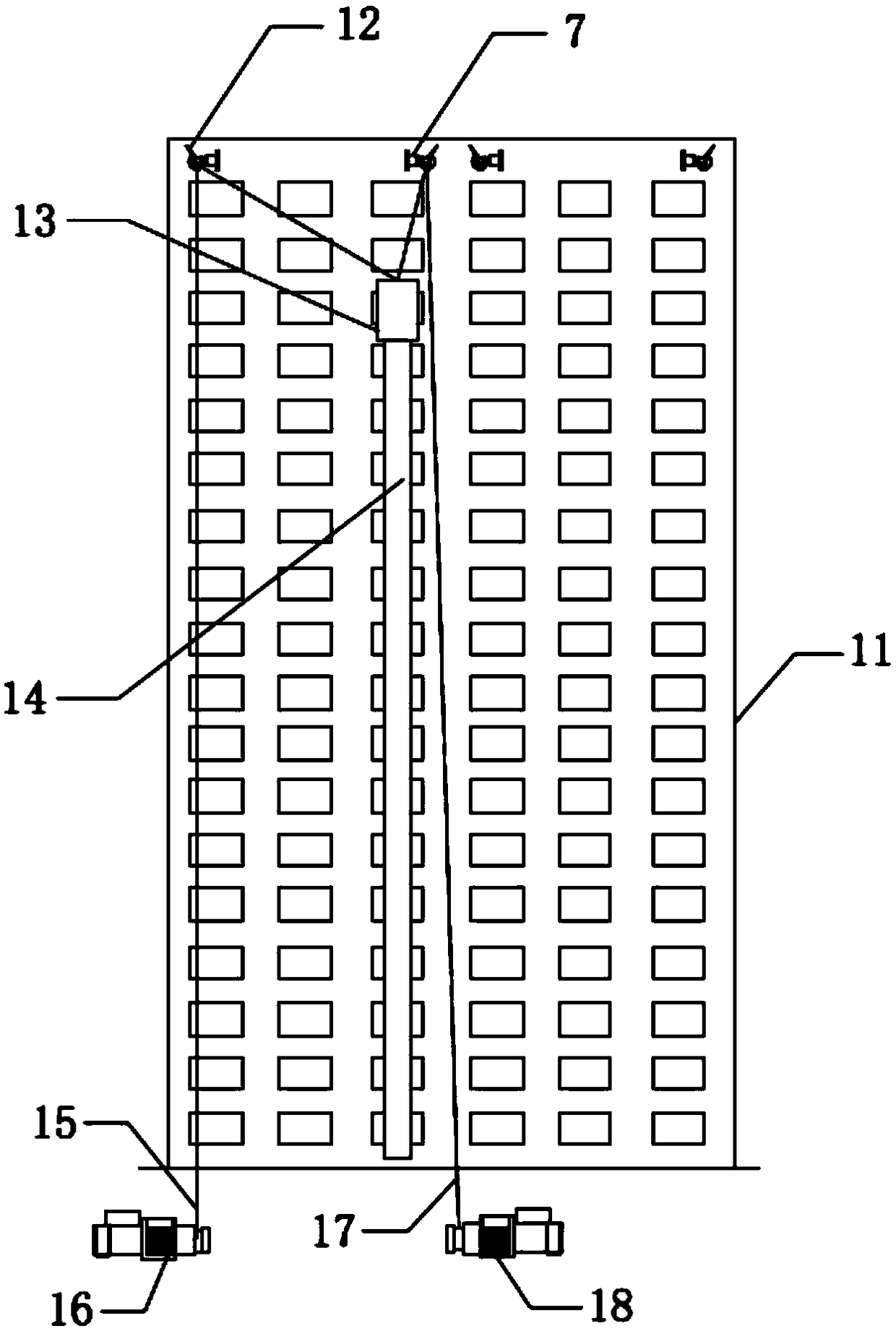
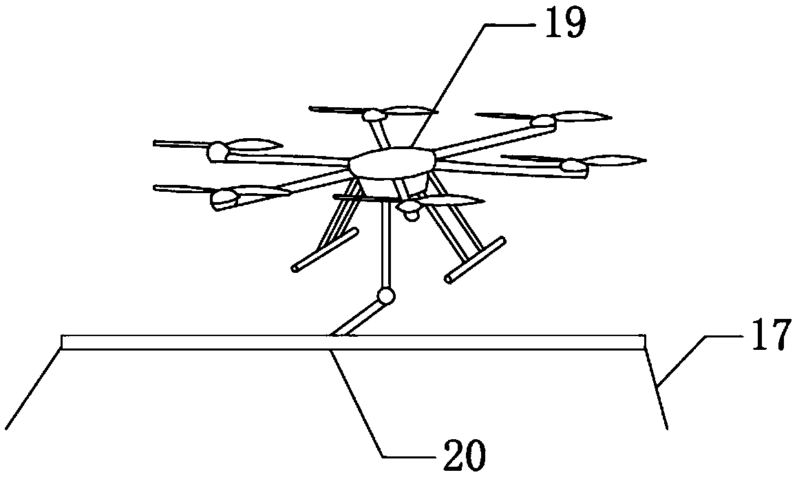
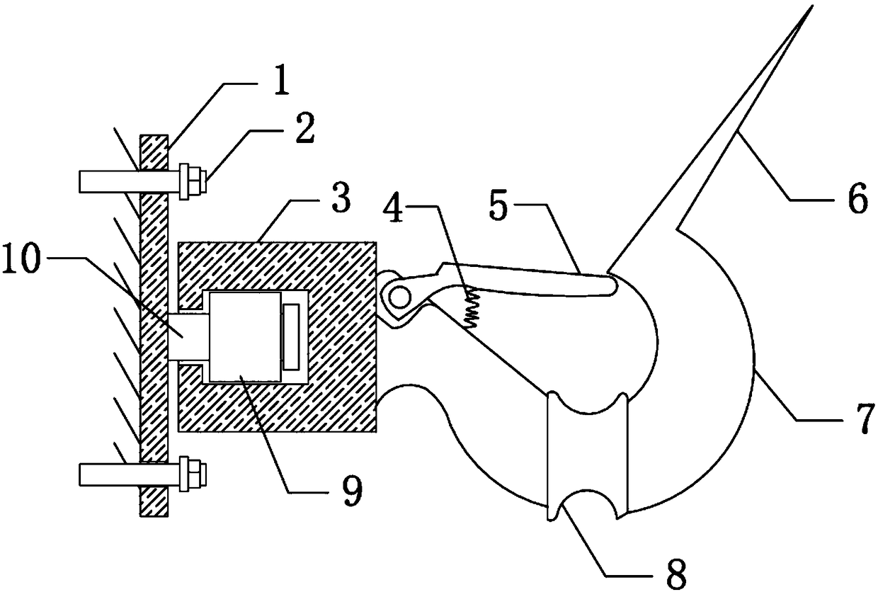
[0031] See Figure 1-6 The present invention provides a technical solution: the high-rise building fire rescue system includes a first hook 7, a second hook 12, an unmanned aerial vehicle 19, a first vehicle-mounted windlass 16 and a second vehicle-mounted windlass 18, the first hook 7 And the second hook 12 are respectively fixedly installed on the external wall of the roof of the building 11. A first rope 15 is installed on the first v...


PUM


Abstract

The invention discloses a high-rise building fire-fighting rescue system. A first rope is installed on a first vehicle-mounted winch, one end of the first rope penetrates through the upper portion ofa second hook, and a hanging cabin is fixedly connected to one end of the first rope; a second rope is installed on a second vehicle-mounted winch, one end of the second rope penetrates through the upper portion of a first hook, and one end of the second rope is fixedly connected to the top of the hanging cabin; the bottom of the hanging cabin communicates with an escape channel; and a supportingrod is fixedly connected to the lower portion of an unmanned aerial vehicle and is of a concave-arc-shaped structure. According to the high-rise building fire-fighting rescue system, a sliding cable system is built through unmanned aerial vehicle installation guiding, the cost is low, the installing speed is high, and quick rescue is easy to achieve; the position of the hanging cabin can be quickly and accurately adjusted through the first vehicle-mounted winch and the second vehicle-mounted winch, and quick rescue is achieved; and rescued people can be transferred into the hanging cabin, theescape channel can be quickly built, and then rescue is achieved.

Description

Technical field [0001] The invention relates to the technical field of building firefighting and rescue, in particular to a high-rise building firefighting and rescue system. Background technique [0002] At present, according to the principles and methods of escape devices, buildings can be roughly divided into the following categories: stair passages, sliding pipes, slow-descent ropes, elevators, and gliding aircraft. There are disadvantages: large building changes, high cost, no smoke and heat prevention, difficult maintenance, or users not only have to overcome psychological fear, but also have to undergo special training, and have stricter requirements on escape posture and arm strength. Or the cost is very expensive, and maintenance is difficult, or the escape speed is slow. Or there are restrictions on floor height, which can only be applied to low floors. And most facilities have fixed entrances, and personnel must move long distances to find the entrance. When firefig...

Claims


Application Information

Patent Timeline
IPC IPC(8): A62B1/20
CPCA62B1/20
Inventor 辛现伟
Owner 辛现伟
Learn More