
Flight operation robot

A technology for working robots and arms, applied in aircraft, unmanned aircraft, aircraft parts, etc., can solve the problems of unstable mechanical structure, built-in battery compartment heating, danger of flying robots, etc., to increase flight balance stability, The effect of improving the mechanical structure and reducing adverse effects

Pending Publication Date: 2019-01-01
SOUTH CHINA UNIV OF TECH +1
View PDF0 Cites 9 Cited by
  • Summary
  • Abstract
  • Description
  • Claims
  • Application Information

AI Technical Summary

Problems solved by technology

However, due to the immature stage of drone technology, the research on flying robots cannot fully meet the needs of performing tasks, including the built-in battery compartment, which is very hot and difficult to replace; the instability of the mechanical structure can easily lead to dangers for flying robots ; Sensors are easily damaged by collisions; single rotor (each arm has only one rotor) has insufficient flight power; the mechanical arm cannot avoid extreme positions or singular points, etc.
These will affect the reliability and stability of the flying operation robot to perform tasks

Method used


Image

  • Flight operation robot
  • Flight operation robot
  • Flight operation robot

Examples


Embodiment

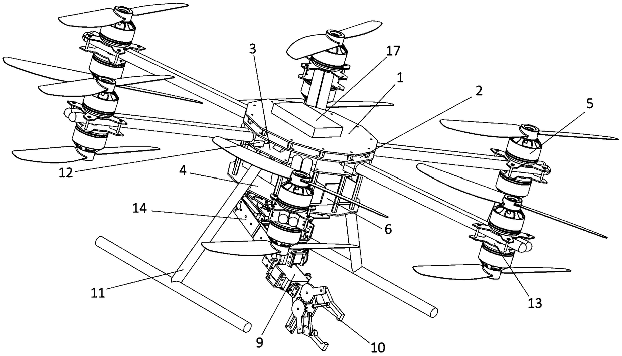
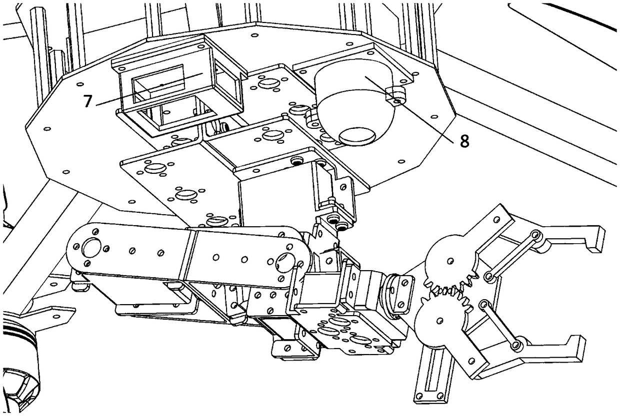
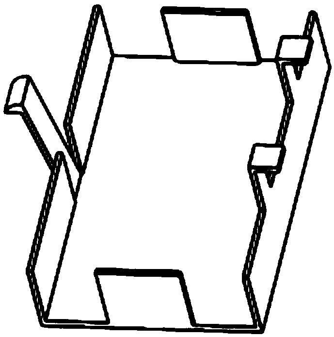
[0024] Such as figure 1 As shown, the present embodiment provides a kind of flying work robot, and this flying work robot comprises UAV body and redundant mechanical arm; The plate (1), the second carbon fiber plate (2), the third carbon fiber plate (3) and the fourth carbon fiber plate (4) are composed of several metal pillars fixed and assembled in parallel, and the third carbon fiber plate (3) is detachably installed There is a battery compartment (6) for placing batteries, located between the third carbon fiber plate (3) and the fourth carbon fiber plate (4); optical flow sensors with housings are detachably installed under the fourth carbon fiber plate (4) (7) and ultrasonic sensor (8); Described machine arm one end is fixed between the second carbon fiber board (2) and the 3rd carbon fiber board (3) by connecting fastener (12), and the other end is connected with up and down rotor and drive The motors (5) of the upper and lower rotors are connected, the redundant mechan...


PUM


Abstract

The invention discloses a flight operation robot. The flight operation robot comprises an unmanned aerial vehicle machine body and a redundancy mechanical arm, wherein the unmanned aerial vehicle machine body comprises a machine body and a plurality of machine arms; the machine body is formed by fixedly assembling a first carbon fibre board, a second carbon fibre board, a third carbon fibre boardand a fourth carbon fibre board through a plurality of metal columns in parallel; a battery bin for placing batteries is detachably mounted below the third carbon fibre board, and the battery bin is positioned between the third carbon fibre board and the fourth carbon fibre board; an optical flow sensor with a housing and an ultrasonic sensor with a housing are detachably mounted below the fourthcarbon fibre board separately; one end of each machine arm is fixedly arranged between the second carbon fibre board and the third carbon fibre board through a connecting fastening part, and the otherend of each machine arm is connected with upper and lower rotors and a motor for driving the upper and lower rotors; the redundancy mechanical arm is mounted below the unmanned aerial vehicle machinebody; and a control device for controlling the flight operation robot is mounted above the first carbon fibre board. The flight operation robot effectively improves firmness and balance stability asa novel design is adopted in mechanical structure.

Description

technical field [0001] The invention relates to the field of unmanned aerial vehicles, in particular to a flying operation robot. Background technique [0002] In recent years, flying operation robots have gradually been applied and developed in various fields, such as military exploration, civil service, power inspection, express transportation and disaster rescue. However, due to the immature stage of drone technology, the research on flying robots cannot fully meet the needs of performing tasks, including the built-in battery compartment, which is very hot and difficult to replace; the instability of the mechanical structure can easily lead to dangers for flying robots ; Sensors are easily damaged by collisions; single rotor (each arm has only one rotor) has insufficient flight power; the mechanical arm cannot avoid extreme positions or singular points, etc. All these will affect the reliability and stability of the flying operation robot to perform tasks. Contents of ...

Claims


Application Information

Patent Timeline
Patent Type & Authority Applications(China)
IPC IPC(8): B64C27/08B64C27/10B64C27/12B64C27/32B64C1/06B64C25/32B64D27/24B64D47/00
CPCB64C1/068B64C25/32B64C27/08B64C27/10B64C27/12B64C27/32B64D27/24B64D47/00B64U10/10B64U50/19
Inventor 张智军周柏李郑陆楠
Owner SOUTH CHINA UNIV OF TECH
Learn More