
A paper-turning mechanism for a platen device

A technology of pressing plate and paper, applied in transportation and packaging, thin material handling, object supply, etc., can solve the problems of slowing down the processing and production progress, difficult to guarantee the position, increasing the production cost of enterprises, etc., to reduce the management and maintenance of forklift trucks. The effect of cost, reduced personnel input, and high degree of automation

Active Publication Date: 2020-04-14
FOSHAN SANSHUI YUSN DECORATION IND
View PDF8 Cites 2 Cited by
  • Summary
  • Abstract
  • Description
  • Claims
  • Application Information

AI Technical Summary

Problems solved by technology

[0002] In the sheet pressing work, for the high-speed pressing production line, manual laying is still used to lay the paper on the upper and lower sides of the board; each high-speed production line needs to be equipped with a professional paper laying technician, and the paper laying work It is a delicate work, which requires very high technical personnel. A little carelessness will cause damage to the paper, resulting in unnecessary losses, increasing the production cost of the enterprise and slowing down the entire processing and production progress.
The paper laying work has relatively high requirements on the position. It is difficult for the technical personnel in charge of laying the paper to ensure the position of each paper, and the operation is time-consuming and labor-intensive.

Method used


Image

  • A paper-turning mechanism for a platen device
  • A paper-turning mechanism for a platen device
  • A paper-turning mechanism for a platen device

Examples


Embodiment Construction

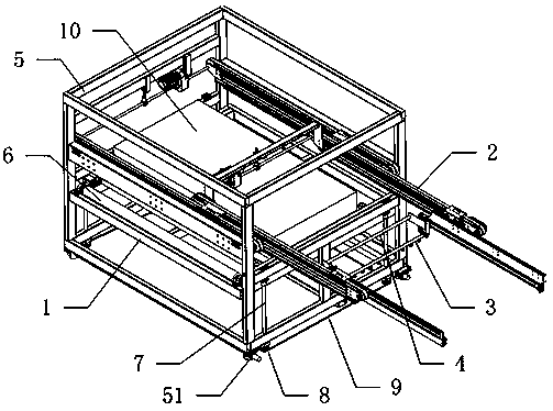
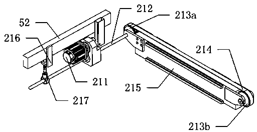
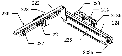
[0023] The present invention provides a paper-turning mechanism for a platen pressing device. In order to make the purpose, technical solution and effect of the present invention clearer and clearer, the present invention will be described in detail below with reference to the accompanying drawings and examples. It should be understood that the specific embodiments described here are only used to explain the present invention, not to limit the present invention. in, figure 2 Only one side of the primary transmission shaft is shown, and the primary synchronous wheel, primary synchronous belt, and primary guide rail are symmetrical about the primary transmission shaft; image 3 Only one side of the secondary transmission shaft is shown, and the secondary synchronous wheel, secondary synchronous belt, secondary guide rail, and first moving block are symmetrical about the secondary transmission shaft; Figure 4 Only one side of the vacuum tube is shown, and the telescopic cylind...


PUM


Abstract

The invention discloses a paper overturning mechanism for a plate pressing device. The mechanism comprises a lifting paper frame capable of moving up and down and used for placing paper, two stretchable parts capable of horizontally stretching out and drawing back at the same time, an absorbing part capable of rotating by 360 degrees and used for absorbing the paper, and a paper pressing part; thestretchable parts are arranged above the lifting paper frame, and are arranged on the left and right sides of the lifting paper frame; the paper pressing part comprises an exhaust pipe, and multipleair nozzles uniformly arranged at the bottom of the exhaust pipe; the paper pressing part is arranged on the back upper side of the absorbing part; exhaust ports of the air nozzles are inclined to theabsorbing part; the two ends of the absorbing part and the two ends of the paper pressing part are slidingly connected to the stretchable parts; and the absorbing part can move up and down relative to the paper pressing part. The paper on the lifting paper frame is absorbed by using the absorbing part; the paper is put on a worktable of the plate pressing device through horizontal extension actions of the stretchable parts; then, another piece of paper is absorbed by the absorbing part; and through rotation, the paper is overturned to be put on the upper surfaces of plates on the worktable tofinish automatic paper paving work on the upper and lower surfaces of the plates, so that the working efficiency is improved.

Description

technical field [0001] The invention relates to the technical field of plate pressing equipment, in particular to a paper turning mechanism for a plate pressing device. Background technique [0002] In the sheet pressing work, for the high-speed pressing production line, manual laying is still used to lay the paper on the upper and lower sides of the board; each high-speed production line needs to be equipped with a professional paper laying technician, and the paper laying work It is a delicate work, which requires very high technical personnel. If you do not pay attention, it will damage the paper, cause unnecessary losses, increase the production cost of the enterprise and slow down the entire processing and production progress. The paper laying work has relatively high requirements on the position. It is difficult for the technicians in charge of laying the paper to ensure the position of each paper, and the operation is time-consuming and labor-intensive. [0003] It c...

Claims


Application Information

Patent Timeline
Patent Type & Authority Patents(China)
IPC IPC(8): B65H5/22B65H5/34
CPCB65H5/222B65H5/34B65H2406/366B65H2701/176
Inventor 郭晓宁
Owner FOSHAN SANSHUI YUSN DECORATION IND
Learn More