
Suspension bridge rear cable anchor head traction device

A technology of traction device and suspension bridge, which is applied to bridges, bridge construction, erection/assembly of bridges, etc. It can solve problems such as fast slipping and falling of back cables, obstruction of guide wheels, and low efficiency of back cable erection, so as to ensure construction safety and save energy. Cost, the effect of ensuring reliability

Pending Publication Date: 2019-01-01
GUANGDONG PROVINCIAL CHANGDA HIGHWAY ENG
View PDF6 Cites 0 Cited by
  • Summary
  • Abstract
  • Description
  • Claims
  • Application Information

AI Technical Summary

Problems solved by technology

In this process, the rear anchor head of the back cable must cross at least one cable tower, and pass through at least one anchorage portal frame, catwalk portal frame, and tower top portal frame, while the current rear anchor head suspension device passes through each portal frame. will be hindered when the guide wheel set is installed, resulting in inefficient back rope erection
Taking a three-span suspension bridge as an example, the main cable of the mid-span part is a parabola with its vertex pointing downwards, so when the back cable passes through the mid-span, there will be a section of distance that is completely downhill. Due to its own gravity, during the downhill journey, the back cable is easy to slide and fall uncontrollably on the catwalk support roller, which affects the safety of the suspension bridge construction

Method used


Image

  • Suspension bridge rear cable anchor head traction device
  • Suspension bridge rear cable anchor head traction device
  • Suspension bridge rear cable anchor head traction device

Examples


Embodiment Construction

[0018] Below, the present invention will be further described in conjunction with the accompanying drawings and specific implementation methods. It should be noted that, under the premise of not conflicting, the various embodiments described below or the technical features can be combined arbitrarily to form new embodiments. .

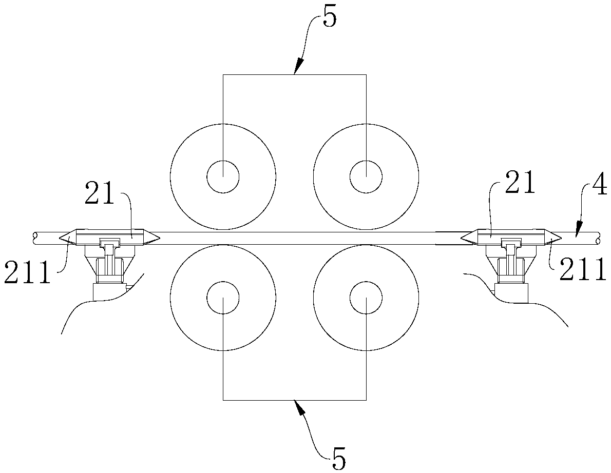
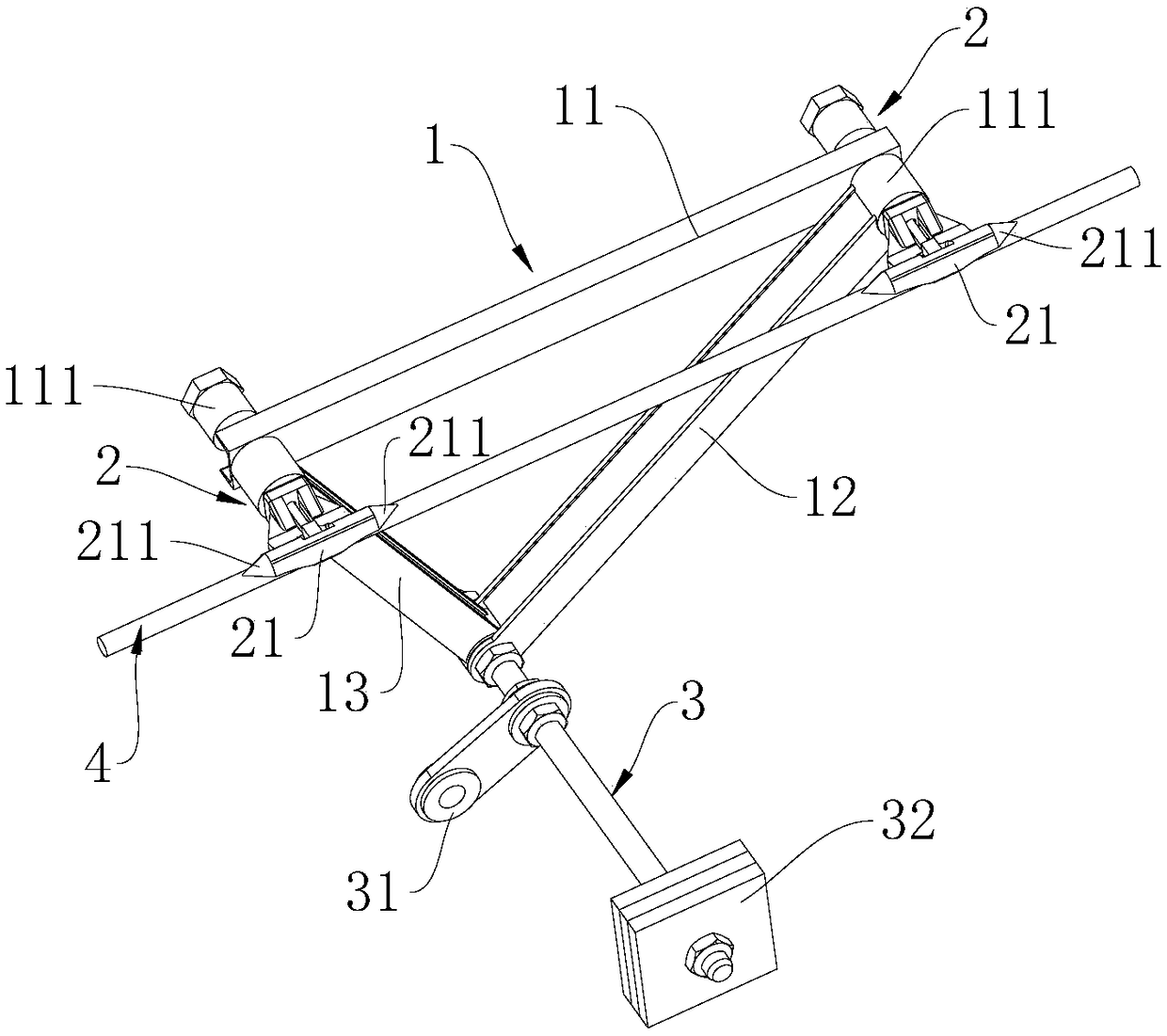
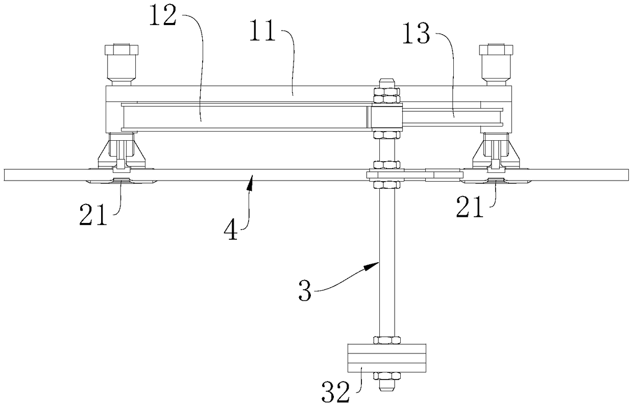
[0019] Such as Figure 1-3 As shown in FIG. 1 , the pulling device for the rear anchor head of the back cable of the suspension bridge provided by the embodiment of the present invention is shown, which at least includes a tripod body 1 and a cable grip 2 . The tripod body 1 includes a first connecting piece 11 , a second connecting piece 12 , and a third connecting piece 13 . The first connecting piece 11 is arranged along the direction parallel to the pulling rope 4, and the two ends of the first connecting piece 11 are provided with a gripping device 2, and the gripping device 2 includes a fixed part, and is connected with the fixing part and exten...


PUM


Abstract

The invention discloses a suspension bridge rear cable anchor head traction device, which at least comprises a tripod body and a cable clasp. The tripod body includes a first connector, a second connector, and a third connector. The first connecting member is arranged in a direction parallel to the traction cable, and two ends of the first connecting member are provided with a cable holder, the cable holder includes a fixing portion and a clamping portion connected with the fixing portion and extending in the circumferential direction of the traction cable; the fixing part is connected with the first connecting part, and the clamping part abuts on the traction cable to clamp the traction cable. The suspension bridge rear cable anchor head traction device can make the back cable rear anchorhead smoothly pass through the guide wheel set of each gantry, and can prevent the back cable from uncontrollable quick sliding and falling on the catwalk support roller.

Description

technical field [0001] The invention relates to the technical field of suspension bridge construction, in particular to a rear anchor head traction device for a back cable of a suspension bridge. Background technique [0002] Suspension bridge, also known as suspension bridge, refers to a bridge whose main load-bearing member of the superstructure is the main cable suspended by the cable tower and anchored on both banks (or at both ends of the bridge). Its cable geometry is determined by the balance of forces and is generally close to a parabola. Many suspenders hang from the cables to hang the bridge deck. Stiffening beams are often set between the bridge deck and the suspenders to form a combined system with the cables to reduce the deflection and deformation caused by the load. [0003] The overall construction sequence of the suspension bridge can be divided into the following steps: install saddles, guide cables across the river, install traction cables, install catwal...

Claims


Application Information

Patent Timeline
Patent Type & Authority Applications(China)
IPC IPC(8): E01D21/00
CPCE01D21/00
Inventor 罗超云张东曾王晓佳崖岗代希华郑波涛童俊豪吴育剑廖国聪杨博文
Owner GUANGDONG PROVINCIAL CHANGDA HIGHWAY ENG
Learn More