Braking device and winch system
A braking device and braking equipment technology, which is applied in hoisting devices, spring mechanisms, etc., can solve the problems of low reliability and inability to achieve flexible deceleration of lifted objects, and achieve fast response, simple structure, The effect of removing the electronic control link
- Summary
- Abstract
- Description
- Claims
- Application Information
AI Technical Summary
Problems solved by technology
Method used
Image
Examples
Embodiment 1
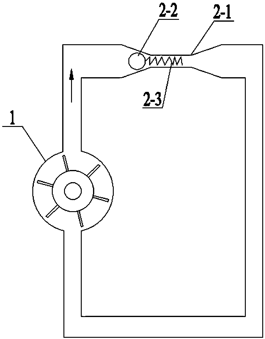
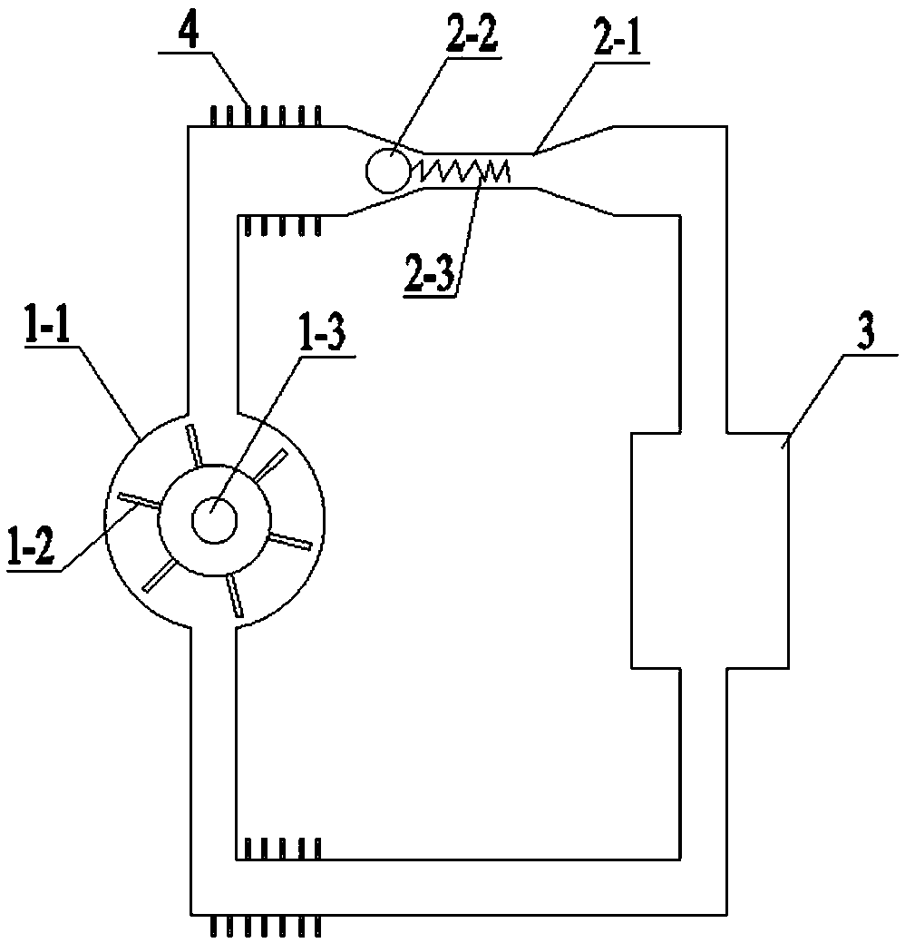
[0024] Such as figure 1 As shown, the present invention provides a braking device, which includes a pumping unit 1 and a cut-off unit, the cut-off unit includes a reducing tube 2-1, a throttle ball 2-2 and an elastic member 2-3, the pump The inlet and outlet of the delivery unit 1 are respectively communicated with the two ends of the reducing pipe 2-1 to form a circulation loop; the pumping unit 1 is connected with the equipment to be braked and used to drive the circulation loop under the drive of the equipment to be braked The liquid working medium circulates; the throttling ball 2-2 is arranged between the variable diameter of the variable diameter tube 2-1 and the pumping unit 1, and is used to block the variable diameter tube 2-1 under the drive of the liquid working medium Diameter reduction; that is to say, the diameter of the throttle ball 2-2 is not less than the inner diameter of the diameter reduction pipe; the two ends of the elastic member 2-3 are respectively co...
Embodiment 2
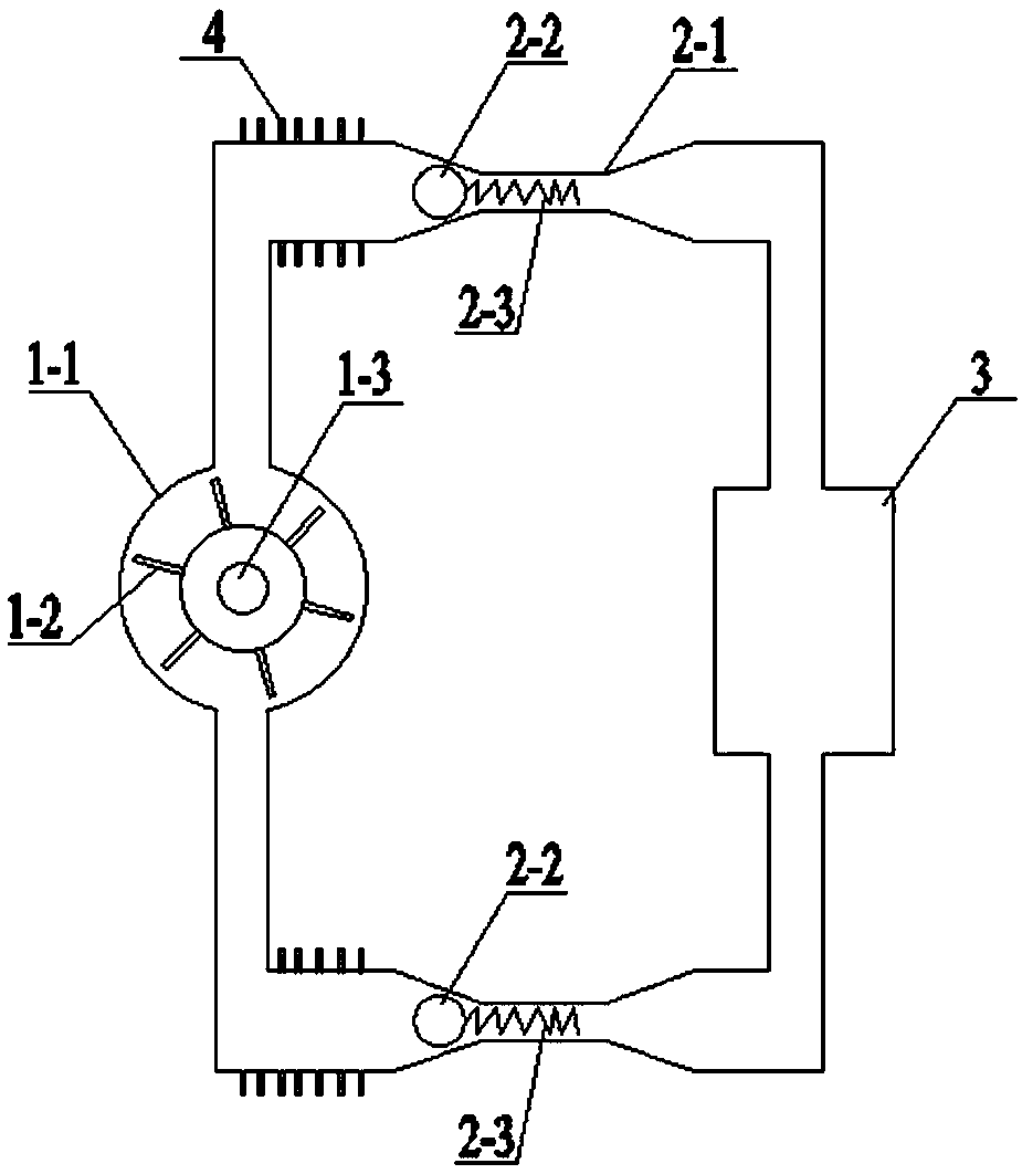
[0036] Such as image 3 As shown, the structure and principle of the braking device in this embodiment are the same as those in Embodiment 1, and will not be repeated in this embodiment.
[0037] The difference is that there are two cut-off units in this embodiment, the pumping unit 1 and the two cut-off units are connected end to end in turn, and the two throttling balls 2-2 are respectively located at both ends of the pumping unit 1 and the corresponding between the diameter reducing places of the reducing pipe 2-1.
[0038] Therefore, when the braking equipment is rotating forward, that is, when the liquid working medium flows clockwise, the upper end of the pumping unit 1 is the outlet and the lower end is the inlet. The throttling ball 2-2, that is, the throttling ball 2-2 on the top will block the variable diameter place of its variable diameter tube 2-1 under the drive of the liquid working medium, and then the braking of the equipment to be braked can be realized.
...
Embodiment 3
[0041] The invention provides a hoisting system, which comprises a hoist, an electromagnetic brake, a controller, a flow velocity detector and the above-mentioned brake device, the flow velocity detector is inserted in the circulation loop, and the controller is connected with the flow velocity detector respectively. It is electrically connected with the electromagnetic brake. The structure and principle of the braking device in this embodiment are the same as those in Embodiment 1 and Embodiment 2, and will not be repeated in this embodiment.
[0042] Thus, when the flow rate detector detects that the flow rate of the liquid working medium in the circulation loop is greater than the specified value, the controller controls the electromagnetic brake to brake the winch; When reaching a certain value, the throttling ball 2-2 will block the reducing pipe 2-1, and the circulation loop will be blocked, so that the pumping unit 1 will be forced to stop, and then the hoisting machine...
PUM
 Abstract
Description
Claims
Application Information
 - R&D
- Intellectual Property
- Life Sciences
- Materials
- Tech Scout
- Unparalleled Data Quality
- Higher Quality Content
- 60% Fewer Hallucinations
Browse by: Latest US Patents, China's latest patents, Technical Efficacy Thesaurus, Application Domain, Technology Topic, Popular Technical Reports.
© 2025 PatSnap. All rights reserved.Legal|Privacy policy|Modern Slavery Act Transparency Statement|Sitemap|About US| Contact US: help@patsnap.com


