
Mining multifunctional illuminating device

A lighting device and multi-functional technology, which is applied to lighting devices, lighting devices, lighting auxiliary devices, etc., can solve the problems of inconvenient use, inability to transmit warning signals, and lack of devices, and achieve good use effects.

Inactive Publication Date: 2019-01-01
LIAONING TECHNICAL UNIVERSITY
View PDF6 Cites 0 Cited by
  • Summary
  • Abstract
  • Description
  • Claims
  • Application Information

AI Technical Summary

Problems solved by technology

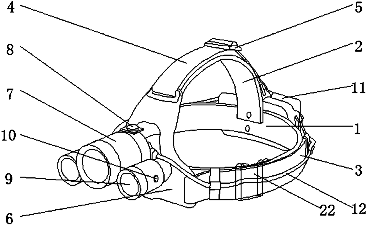
[0002] Head-mounted lighting is a small lighting device composed of head-mounted stable equipment and light-emitting equipment that is easy to move and work. It was invented to meet the needs of special units and industries for work lighting. It can be used in conjunction with safety helmets. Good waterproof, dustproof, explosion-proof, anti-static performance, is widely used in various mining operating environments, but the current mining head-mounted lighting still has some shortcomings when used: the mining operation area is located The underground environment is complex and changeable. Ordinary head-mounted lighting for mining only has the function of lighting. In an emergency, the warning signal cannot be transmitted to a distant place through the light; A device for continuous sound transmission; ordinary mining head-mounted lighting is often fixed, and the irradiation angle cannot be adjusted, which is inconvenient to use; for this reason, we propose a mine-used multifunctional lighting device

Method used


Image

  • Mining multifunctional illuminating device
  • Mining multifunctional illuminating device
  • Mining multifunctional illuminating device

Examples


Embodiment Construction

[0031] The present invention will be further described below in combination with specific embodiments.

[0032] In the description of the present invention, it should be noted that the terms "upper", "lower", "inner", "outer", "front end", "rear end", "both ends", "one end", "another end" The orientation or positional relationship indicated by etc. is based on the orientation or positional relationship shown in the drawings, and is only for the convenience of describing the present invention and simplifying the description, rather than indicating or implying that the referred device or element must have a specific orientation, use a specific Azimuth configuration and operation, therefore, should not be construed as limiting the invention.

[0033] In the description of the present invention, it should be noted that, unless otherwise specified and limited, the terms "installed", "set with", "connected", etc. should be understood in a broad sense, such as "connected", which may ...


PUM


Abstract

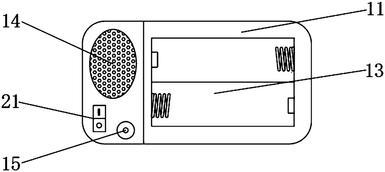
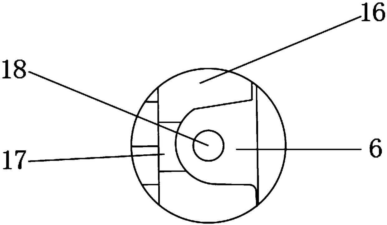
The invention provides a mining multifunctional illuminating device, and belongs to the technical field of mining auxiliary equipment. The mining multifunctional illuminating device comprises an outerring head support, a top head support, an illuminating assembly and a battery holder, the top head support is arc-shaped, the two ends of the top head support are separately connected with the outerring head support, the two connection positions are a first connection position and a second connection position separately, the outer ring head support is annular, the illuminating assembly comprisesa fixed lamp bracket, a rotating lamp holder, a strong-light searchlight, an auxiliary warning lamp and a connecting bolt, the fixed lamp bracket is arranged at the first connection position, the fixed lamp bracket is movably connected with the rotating lamp holder through the connecting bolt, the rotating lamp holder is provided with the strong-light searchlight and the auxiliary warning lamp, the battery holder is mounted at the second connection position, and is connected with the rotating lamp holder through a power wire, and the battery holder is provided with a rechargeable battery jar,a sound amplifying loudspeaker and a charging hole. The lamplight illuminating angle of the mining multifunctional illuminating device is adjustable, warning signals can be transmitted, sound transmission can be implemented continuously, and the mining multifunctional illuminating device can be used independently and can also be used with a helmet.

Description

technical field [0001] The invention relates to the technical field of mine auxiliary equipment, in particular to a mine multifunctional lighting device. Background technique [0002] Head-mounted lighting is a small lighting device composed of head-mounted stable equipment and light-emitting equipment that is easy to move and work. It was invented to meet the needs of special units and industries for work lighting. It can be used in conjunction with safety helmets. Good waterproof, dustproof, explosion-proof, anti-static performance, is widely used in various mining operating environments, but the current mining head-mounted lighting still has some shortcomings when used: the mining operation area is located The underground environment is complex and changeable. Ordinary head-mounted lighting for mining only has the function of lighting. In an emergency, the warning signal cannot be transmitted to a distant place through the light; A device for continuous sound transmissio...

Claims


Application Information

Patent Timeline
IPC IPC(8): F21L4/00F21V17/12F21V21/084F21V21/14F21V33/00F21W131/402
Inventor 贾宝山程禹熙贾牛骏张勇志王一明陈佳慧付铄钦
Owner LIAONING TECHNICAL UNIVERSITY
Learn More