
Arc-extinguishing structure of direct-current contactor

A DC contactor and arc extinguishing technology, applied in relays, electromagnetic relays, detailed information of electromagnetic relays, etc., can solve problems such as continuous arcing of arcs

Pending Publication Date: 2019-01-01
SHANGHAI LIANGXIN ELECTRICAL
View PDF1 Cites 0 Cited by
  • Summary
  • Abstract
  • Description
  • Claims
  • Application Information

AI Technical Summary

Problems solved by technology

However, when the DC contactor is used in a high-voltage situation, there will be a problem of continuous arcing when it is broken.

Method used


Image

  • Arc-extinguishing structure of direct-current contactor
  • Arc-extinguishing structure of direct-current contactor
  • Arc-extinguishing structure of direct-current contactor

Examples


Embodiment 1

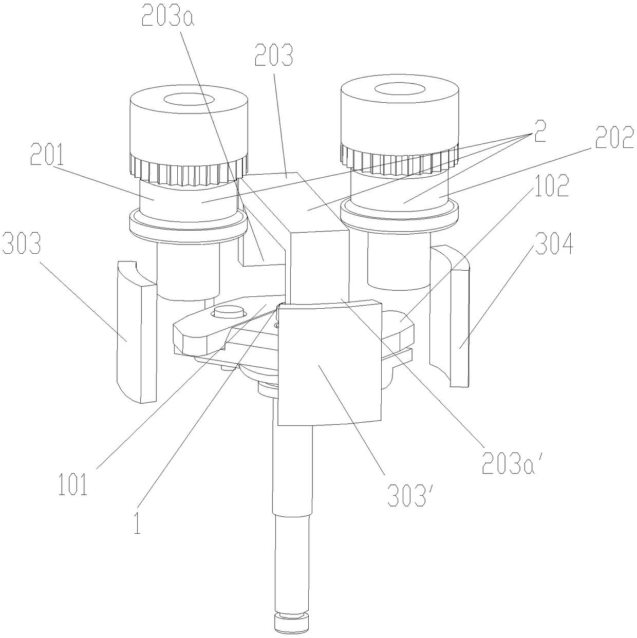
[0021] as attached figure 1 As shown, an embodiment provided by the present invention is a DC contactor arc extinguishing structure, which includes a moving contact assembly 1 and a static contact assembly 2, the moving contact assembly 1 and the static contact assembly 2 The engagement and disengagement of the DC contactor can control the on-off of the DC contactor. The moving contact assembly 1 includes moving contact one 101 and moving contact two 102, the static contact assembly 2 includes static contact one 201, static contact two 202 and static contact three 203, the static contact Head 1 201 and static contact 2 202 correspond to the moving contacts on one of the diagonal lines at both ends of the moving contact 101 and moving contact 2 102 respectively, and the two moving contacts of the moving contact 3 203 The static contacts 203a, 203a' are respectively connected in series with the movable contacts at the other two ends of the diagonal lines at the two ends of the ...

Embodiment 2

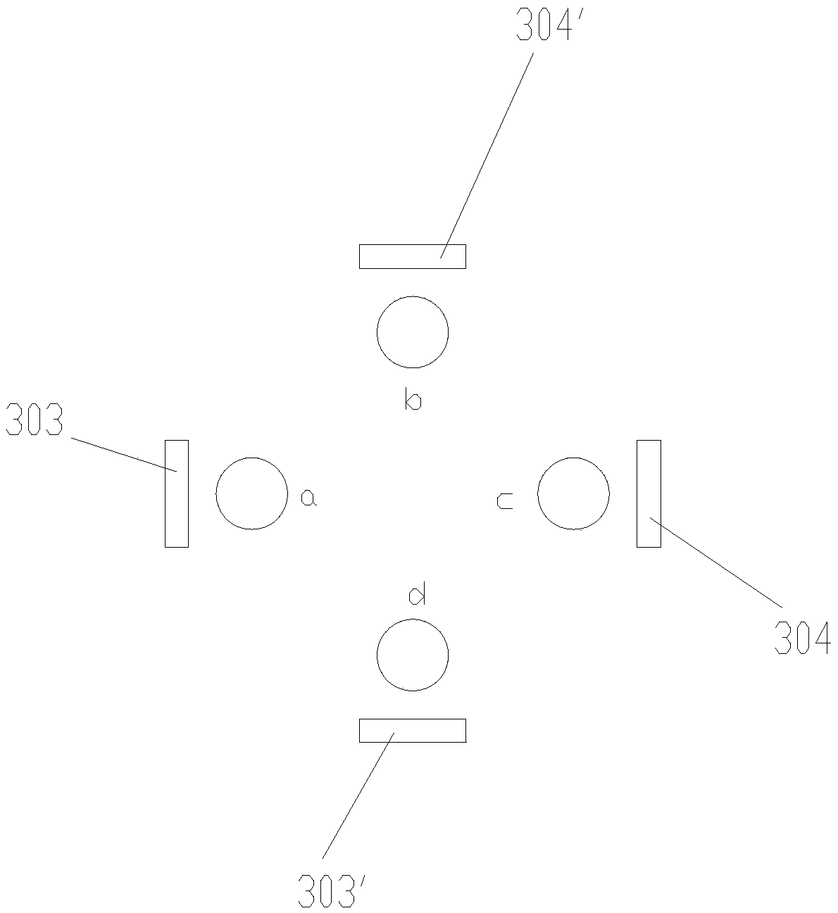
[0026] as attached image 3 As shown, the present invention also provides an embodiment in which the third permanent magnet 303, 303' and the fourth permanent magnet 304, 304' can also be square, and other structures are the same as in the first embodiment.

Embodiment 3

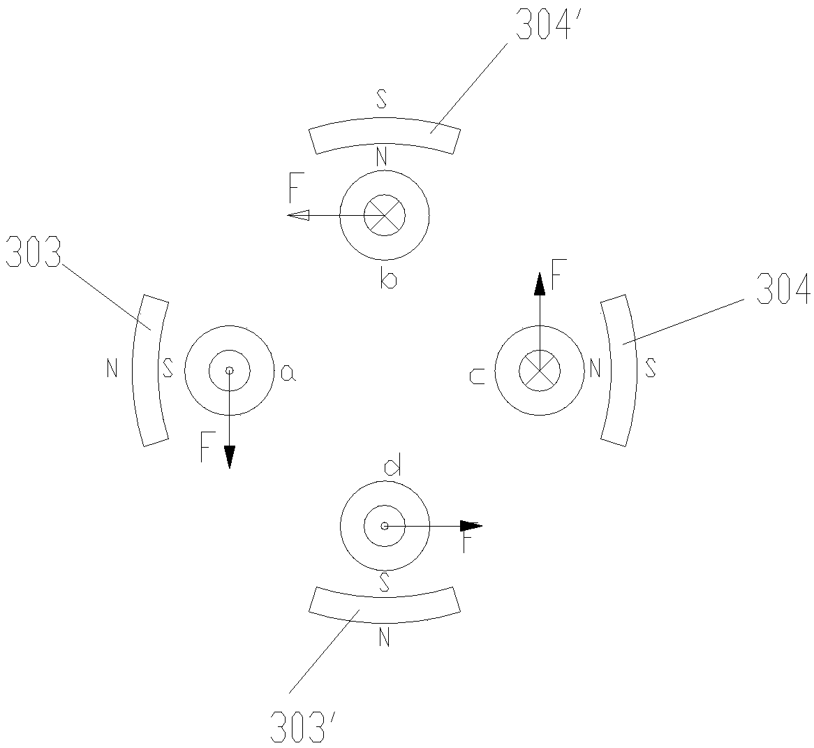
[0028] as attached Figure 4 As shown, in an embodiment provided by the present invention, the four fractures a, b, c, d are sequentially connected end to end to form two permanent magnets on the outside of the area, the moving contact assembly 1 and the static When the contact assembly 2 is engaged, the permanent magnets on the outside of the fracture in the same current direction have the same magnetic pole direction on the fracture surface side, and the magnetic pole directions on the fracture surface side of the permanent magnets on the outside of the fracture in different current directions are different.

[0029] The four fractures a, b, c, d are connected end to end to form two permanent magnets on the outside of the area, the N pole to the S pole of the permanent magnets are from the inside to the outside, and the two permanent magnets are permanent magnets The first 301 and the second permanent magnet 302, the first permanent magnet 301 and the second permanent magnet...


PUM


Abstract

Provided in the invention is an arc-extinguishing structure of a direct-current contactor. The arc-extinguishing structure comprises a movable contact assembly (1) and a static contact assembly (2) that are connected in series to form a direct-current contactor main loop having four fractures (a, b, c, and d); and the four fractures (a, b, c, and d) are connected successively in an end-to-end modeto form a region and at least two permanent magnets are arranged at the outer side of the region. When the moving contact assembly (1) and the static contact assembly (2) are connected, magnetic poledirections, at sides of the fracture surfaces, of the permanent magnets at the outer sides of the fractures in same current directions are same and magnetic pole directions, at sides of the fracturesurfaces, of the permanent magnets at the outer sides of the fractures in different current directions are different. According to the arc-extinguishing structure, the main loop employs the single-pole four-breakpoint series connection mode; permanent-magnet magnetic blowing out for arc extinguishing is carried out in the single-pole contactor having the four fractures, so that the size of the contactor is not increased and the connection and breaking capacity of the direct-current contactor is enhanced substantially. The main loop voltage with the higher breaking capacity can be connected. Objectives of small size and high breaking are achieved.

Description

technical field [0001] The invention belongs to the technical field of DC contactors, and in particular relates to an arc extinguishing structure of a DC contactor. Background technique [0002] DC contactors are widely used in vehicles that use batteries as energy sources to control multiple actions such as vehicle startup and speed regulation. With the rapid development of electric vehicles, the market demands higher and higher rated voltages for DC contactors. Since the volume of the DC contactor is determined by the rated current, and the contact space is closed. The most important factor affecting the on-off capability of the DC contactor is the on-off voltage. The higher the on-voltage of the DC contactor, the harder it is to turn on and off normally. The existing moving contact scheme has been difficult to meet To connect and break the high voltage demand. [0003] Chinese patent authorization announcement number CN206250126U discloses a DC contactor. The DC contac...

Claims


Application Information

Patent Timeline
Patent Type & Authority Applications(China)
IPC IPC(8): H01H50/38H01H9/44
CPCH01H9/443H01H50/38
Inventor 李强李冰杨园龚祚勇于贻鹏
Owner SHANGHAI LIANGXIN ELECTRICAL
Learn More