Universal Circuit Breaker Panel Contact System

A technology of circuit breaker board and contact system, which is applied to circuit breaker contacts, circuit breaker parts, etc., can solve the problems of short electrical life, low current withstand capacity, and low breaking capacity of contacts, and improve the reliability of action. high performance, high space utilization, and improved current-carrying capacity

Active Publication Date: 2017-04-05
无锡惠晟精密元器件有限公司
View PDF6 Cites 0 Cited by
  • Summary
  • Abstract
  • Description
  • Claims
  • Application Information

AI Technical Summary

Problems solved by technology

[0007] The purpose of the present invention is to provide a universal circuit breaker plate contact system, which solves the problem of reducing body temperature in the prior art, the number of circuits of the contact system is small, the available space is small, and the heat dissipation and load bearing are short-term resistant. Low current capacity, low breaking capacity, asynchronous breaking and opening, the contacts are not burned at the same time, the electrical life of the contacts is short, and it is impossible to realize the miniaturization, light weight and large capacity of the circuit breaker.

Method used


Image

  • Universal Circuit Breaker Panel Contact System
  • Universal Circuit Breaker Panel Contact System
  • Universal Circuit Breaker Panel Contact System

Examples


Embodiment 1

[0064] The insulating expansion plug 6 of Embodiment 1 is used for insulation, heat insulation, positioning, and carrying double springs (ie, the outer spring 40 and the inner spring 42), and the upper stepped cylindrical cylinder 50 and cylinder 51 are used for the inner spring 42 and the outer spring respectively. 40 limit (anti-shaking), and after the insulating expansion bolt 6 is heated and expanded, the gap becomes smaller, preventing the two springs from being bitten to death by the insulating expansion bolt 6;

[0065] see Figure 9 The structure of Embodiment 2 of the insulating expansion plug 6 is that it includes a tapered cylinder 55 that is plugged and fitted with the tapered hole 63 of the contact piece 3, and a lower narrow straight groove 54 is opened in the axial direction on the circumference of the tapered cylinder 55; The tapered cylinder 55 is connected to the cylinder 51 through the intermediate body 53, and the circumference of the cylinder 51 is also pr...

Embodiment 2

[0066] The insulating expansion bolt 6 of embodiment 2 is used for insulation, heat insulation, positioning, and carrying a single spring. The upper narrow straight groove 52 is used for limiting (anti-shaking) to the spring 5. After the insulating expansion bolt 6 is heated and expanded, the gap becomes larger. Small, to prevent the spring 5 and the insulating expansion bolt 6 from being seized.

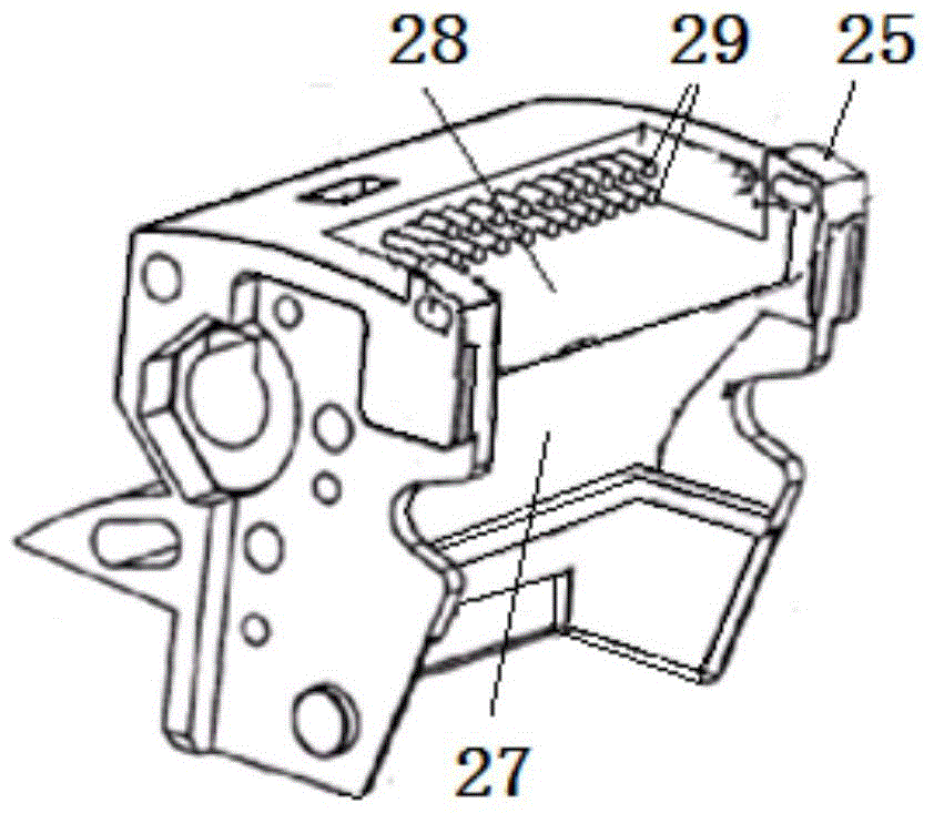
[0067] refer to Figure 10 , is another structural form of the busbar 1, called the busbar 29, the rear end of the busbar 29 is a cylinder, and the front end of the busbar 29 is a plate shape.

[0068] The working principle of the present invention is,

[0069]The opening groove 60 of the contact piece 3 removes the middle connecting plate part of the existing structure, and directly overlaps with the lower mounting hole 63, which shortens the distance and reduces the weight and increases the compensation effect of the short-circuit current electromotive force; the upper welding jo...


PUM


Abstract

The invention discloses a plate type contact system of a conventional circuit breaker. The plate type contact system comprises a moving contact group and a contact support, the moving contact group is formed by the connection of a busbar, a flexible connection, and contact sheets in sequence, the moving contact group is arranged in the contact support, the contact support comprises a spring support body, two sides of the spring support body are respectively provided with a lug, the upper parts of the contact sheets are positioned in U-shaped grooves between the two lugs, the upper parts of the contact sheets are supported in lug holes of the lugs at two sides via an upper supporting shaft, two sides of the spring support body are symmetrically and fixedly provided with baffle pieces, a central rotation shaft penetrates through the central parts of the contact sheets and are supported at the baffle pieces at two sides, a U-shaped contact cover is retained at the front surface of connecting positions of the contact sheets and the flexible connection, and a U-shaped insulation guard board is retained at the backside of the flexible connection. According to the plate type contact system, the structure is simple, the adaptability is high, and the work is reliable.

Description

technical field [0001] The invention belongs to the technical field of low-voltage power distribution appliances, and relates to a plate contact system of a universal circuit breaker. Background technique [0002] Chinese patent 200510025637.6 discloses a moving contact structure of a circuit breaker. In order to improve the short-term withstand current, the number of contact fingers is increased in the contact support, and the specific implementation is to remove the isolation barrier between the contact fingers and the contact support. The contact fingers are separated by using fixed brackets and grids, and the contact fingers are increased by thinning the isolation grid to increase the accommodation space of the contacts, thereby increasing the number of contacts. There is following shortcoming in this method and prior art: [0003] 1) The thickness of the barrier sheet in this structure is generally compressed to the range of 0.8-1mm, and the thermoplastic material is u...

Claims


Application Information

Patent Timeline
Patent Type & Authority Patents(China)
IPC IPC(8): H01H73/04
CPCH01H73/04
Inventor 王小玲
Owner 无锡惠晟精密元器件有限公司
Why Eureka
Try Eureka