
Relay protection device with dual-protection function

A relay protection device and double protection technology, applied in emergency protection circuit devices, emergency protection devices with automatic disconnection, circuit devices, etc., can solve the problem that the moving contact and the static contact cannot move relative to each other, and the circuit breaker cannot be closed Protection, staff accidental touch and other issues, to achieve protection stability, improve service life, and increase the effect of service life

Pending Publication Date: 2020-04-10
DATANG SHAANXI POWER GENERATION
View PDF0 Cites 0 Cited by
  • Summary
  • Abstract
  • Description
  • Claims
  • Application Information

AI Technical Summary

Problems solved by technology

[0003] The existing relay protection device is equipped with a main body, and the front of the main body is provided with a panel. Under long-term use, the main body will generate a large amount of heat, which affects the stability of its operation. In this way, during maintenance, the operator needs to go around to the rear to complete the plugging and unplugging of the wiring plug, which is extremely inconvenient and may cause accidental contact by the staff
Moreover, the current relay protection devices generally use the relative movement between the moving contact and the static contact to achieve relay protection. Once the moving contact is damaged in this structure, it will cause the moving contact and the static contact to be separated. Due to the lack of protection measures, it will not be possible to realize the circuit breaker or close protection, which will affect the safety.

Method used


Image

  • Relay protection device with dual-protection function
  • Relay protection device with dual-protection function
  • Relay protection device with dual-protection function

Examples


Embodiment Construction

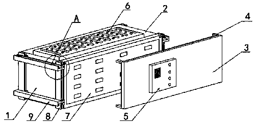
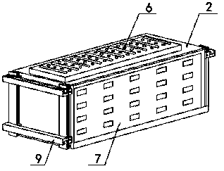
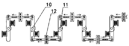
[0029] see Figure 1-8 , in an embodiment of the present invention, a relay protection device with dual protection functions includes a main body 1, an outer protection mechanism and an inner double safety control mechanism, wherein the outer protection mechanism is provided outside the main body, and the The interior of the main body is provided with the internal double-safety control mechanism, which is characterized in that the internal double-safety control mechanism includes n control unit assemblies arranged in the main body along the length direction of the main body, and the i-th control Between the unit assembly 10 and the i+1th control unit assembly 11 adjacent to it is configured as an on-off contact assembly 12 for controlling the on-off of the circuit, wherein the on-off contact assembly 12 is formed by the ith The contact 13 on the control unit assembly 10 is composed of the contact 13 on the i+1th control unit assembly 11. When performing the on-off action, the ...


PUM


Abstract

The invention relates to the technical field of relay protection. The invention discloses a relay protection device with a dual protection function. According to the invention, when an on-off action is carried out, the contact on an ith control unit assembly and the contact on an (i+1)th control unit assembly move towards each other or away from each other at the same time relative to each other so as to achieve on-off control, therefore, dual protection of on-off can be realized, and the protection performance is improved; and even if the action of one contact goes wrong, the other contact can also realize action disconnection, so that the safety of on-off is effectively improved, and the on-off capability is improved; and the control unit assembly adopts the structural design, on-off control can be well achieved, meanwhile, the structure can be conveniently arranged in the length direction of the main body, and control and arrangement of a plurality of interface contacts can be achieved.

Description

technical field [0001] The invention relates to the technical field of relay protection, in particular to a relay protection device with dual protection functions. Background technique [0002] Relay protection equipment is used in the power system. When the power components in the power system or the power system itself fail to endanger the operation of the power system safety system, the relay protection equipment is used to send a warning signal to the operating personnel on duty, or directly to all An automated measure and device in which a controlled circuit breaker issues a trip command to terminate the development of these events. [0003] The existing relay protection device is equipped with a main body, and the front of the main body is provided with a panel. Under long-term use, the main body will generate a large amount of heat, which affects the stability of its operation. In this way, during maintenance, the operator needs to go around to the rear to complete t...

Claims


Application Information

Patent Timeline
Patent Type & Authority Applications(China)
IPC IPC(8): H02H3/05H02H3/02H05K7/20
CPCH02H3/05H02H3/02H05K7/209
Inventor 韩军花曹小行葛粤杜小军孟新刘皓
Owner DATANG SHAANXI POWER GENERATION
Learn More