
Steam cycling and energy-saving device

An energy-saving equipment and steam technology, which is applied in the field of steaming cabinets, can solve problems such as steaming cabinet explosion, loss of steam, waste of steam heat, etc., and achieve the effects of eliminating safety accidents, shortening steaming time, and increasing use safety

Inactive Publication Date: 2019-01-04
中山市多创电器设备有限公司
View PDF0 Cites 5 Cited by
  • Summary
  • Abstract
  • Description
  • Claims
  • Application Information

AI Technical Summary

Problems solved by technology

[0002] The traditional steam cabinet has its own pressure relief valve. When the pressure inside the steam cabinet reaches a certain level, it will start to release the pressure and discharge excess steam to ensure that the steam cabinet will not be damaged. When the pressure relief valve discharges steam, the steam The interior of the cabinet also needs new steam input to fill the heat brought by the exhausted steam. In this way, although the pressure relief valve protects the cabinet body, a large amount of steam is lost at the same time, and the steam also takes away the corresponding heat. , In this way, when steaming food once, a considerable amount of steam heat will be wasted in vain, so the energy of the corresponding steam generated will also be wasted. Once the pressure relief valve is stuck by oil, the steamer will The steam in the steamer cannot be discharged, so the pressure of the steamer will increase, resulting in damage to the steamer or the safety hazard of the steamer being exploded by pressure. The surface temperature of the steamer is affected by the steam. The surface temperature is high, and scald accidents are prone to occur

Method used


Image

  • Steam cycling and energy-saving device
  • Steam cycling and energy-saving device
  • Steam cycling and energy-saving device

Examples


Embodiment Construction

[0019] In order to make the technical means, creative features, goals and effects achieved by the present invention easy to understand, the present invention will be further described below in conjunction with specific embodiments.

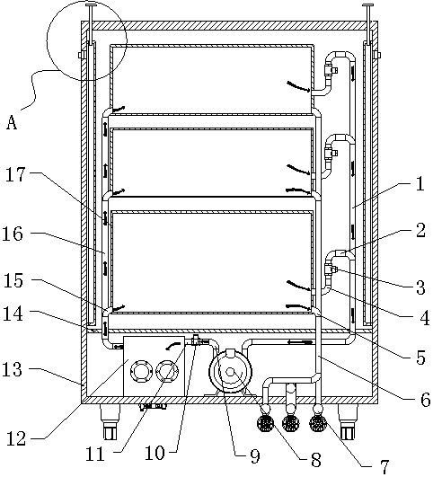
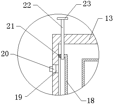
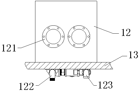
[0020] see Figure 1-Figure 3 , the present invention provides a technical solution: a steam cycle energy-saving equipment, including a device body, a circulation mechanism and a heat insulation mechanism, the device body includes a water outlet pipe 5, a drainage pipe 6, a drainage gate valve 7, a steam cabinet 13, a partition 14 and Steaming chamber 17, dividing plate 14 is installed in steaming cabinet 13 inner lower side, steaming chamber 17 is installed in steaming cabinet 13 inside and steaming chamber 17 is arranged on dividing plate 14 upper side, outlet pipe 5 is installed in steaming chamber 17 right end face lower side and The other end of the outlet pipe 5 is connected to the drain pipe 6 through a pipe joint, the drain pipe 6 is arran...


PUM


Abstract

The invention discloses a steam cycling and energy-saving device including a device body, a circulation mechanism and a heat insulation mechanism. The main body of that device includes an outlet pipe,a drainage pipe, a drain gate valve, a steam cabinet, partitions and steam chambers, the circulation mechanism includes a steam outlet conduit, a steam outlet pipe I, a one-way check valve, a steam outlet pipe II, an exhaust fan, a steam line one, a one-way check valve II, a steam transmission pipe II, a steam generator, a steam inlet pipe and a steam outlet pipe, the heat insulation mechanism isinstalled on the left end surface of the steam cabinet. The heat insulation mechanism comprises a water storage cover, a water adding hole, a plug, a sealing gasket, a hollow pipe and a flange. Compared with the prior art, the heat insulation mechanism has the following beneficial effects: waste of energy is reduced, efficiency of a steam cabinet is improved, use safety of the steam cabinet is increased, service life of the steam cabinet is prolonged, and the purpose of heat insulation and scald prevention is achieved.

Description

technical field [0001] The invention is a steam cycle energy-saving device, which belongs to the technical field of steam cabinets. Background technique [0002] The traditional steam cabinet has its own pressure relief valve. When the pressure inside the steam cabinet reaches a certain level, it will start to release the pressure and discharge excess steam to ensure that the steam cabinet will not be damaged. When the pressure relief valve discharges steam, the steam The interior of the cabinet also needs new steam input to fill the heat brought by the exhausted steam. In this way, although the pressure relief valve protects the cabinet body, a large amount of steam is lost at the same time, and the steam also takes away the corresponding heat. , In this way, when steaming food once, a considerable amount of steam heat will be wasted in vain, so the energy of the corresponding steam generated will also be wasted. Once the pressure relief valve is stuck by oil, the steamer w...

Claims


Application Information

Patent Timeline
Patent Type & Authority Applications(China)
IPC IPC(8): A47J27/04A47J27/16A47J36/00F22B1/28
CPCA47J27/04A47J27/16A47J36/00A47J2027/043F22B1/28
Inventor 鲍继勇徐建云刘文君
Owner 中山市多创电器设备有限公司
Learn More