Spinal fusion cage

A fusion device and implanter technology, used in spinal implants, joint implants, joint implants, etc., can solve the problem of radiation damage to patients, achieve radiation reduction, easy operation and strong practicability Effect

Pending Publication Date: 2019-01-04
CHUANGHUI MEDICAL EQUIP JIANGSU
View PDF0 Cites 1 Cited by
  • Summary
  • Abstract
  • Description
  • Claims
  • Application Information

AI Technical Summary

Problems solved by technology

[0003] The technical problem to be solved by the present invention is to overcome the defects of the prior art and provide a spinal fusion device implanter, which solves the problem that

Method used


Image

  • Spinal fusion cage
  • Spinal fusion cage
  • Spinal fusion cage

Examples


Embodiment

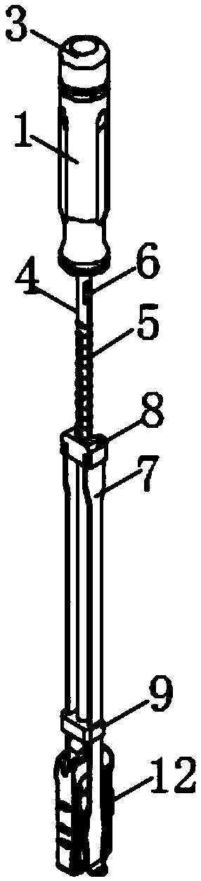
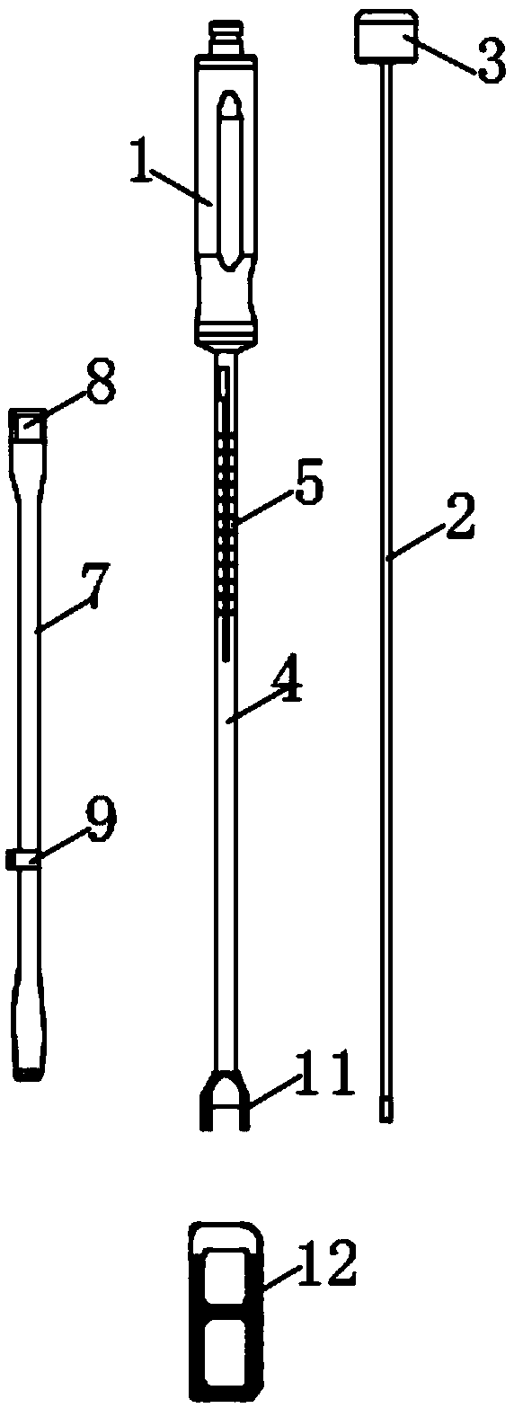
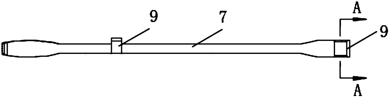
[0021] Such as Figure 1-7 As shown, the spinal fusion implanter includes a handle 1, the bottom of the handle 1 is fixedly connected with a sleeve 4, the outside of the sleeve 4 and the end close to the handle 1 is provided with a scale line 5, the outside of the sleeve 4 and close to the handle 1 There are two block grooves 6 symmetrically, and the end of the sleeve 4 far away from the handle 1 is fixedly connected with the fuser connector 11, the sleeve 4 and the handle 1 are both hollow structures, and the inside of the handle 1 is inserted with a hanging rod 2. The hanging rod 2 passes through one end of the handle 1 and extends to the inside of the casing 4. The end of the hanging rod 2 close to the handle 1 is fixedly connected to the tail cap 3, and the outer side of the casing 4 is slidingly connected to the rear fixing seat 8. And the inside of the rear fixed seat 8 is symmetrically provided with two limit blocks 10, the limit blocks 10 are all stuck in the block gro...


PUM


Abstract

A spinal fusion cage implant is disclosed, including a handles. A sleeve is fixedly connected to the bottom of the handle, an outer side of the sleeve and an end adjacent to the handle are provided with a graduation mark, two stopper grooves are symmetrically arranged on the outer side of the sleeve and close to the handle, and an end of the sleeve away from the handle is fixedly connected with afuser connecting head. The sleeve and handle are hollow structure, and a lifting lever is inserted into the handle. The lifting lever is pierced from one end of the handle and extends into the interior of the sleeve, a tail cap is fixedly connected to an end of that lifting rod close to the handle. The cannula is slidably connected with a posterior fixation seat on the outside, and two limiting blocks are symmetrically arranged inside the posterior fixation seat. The invention has simple and novel structure, strong practicability, simple and quick operation, and the novel spinal fusion cage implantation device does not need fluoroscopy to determine the implantation depth of the fusion cage when implantation, reduces radiation to the patient body, and is convenient to operate.

Description

technical field [0001] The invention belongs to the technical field of medical instruments, in particular to a spinal fusion device implanter. Background technique [0002] In the existing social life, with the continuous improvement of the social level, people's travel and work have been greatly improved, and people can complete a lot of work without going out, but this leads to long-term sedentary people. During the long-term sedentary process, the spine Some lesions often occur, and fusion cages are widely used in the treatment of the spine. The fusion device needs to be implanted in the intervertebral space of people. The spinal fusion device implanter of the prior art needs to use X-ray perspective to determine the fusion device implantation depth during use, and the X-ray has radiation damage to the patient. Contents of the invention [0003] The technical problem to be solved by the present invention is to overcome the defects of the prior art and provide a spinal ...

Claims


Application Information

Patent Timeline
IPC IPC(8): A61F2/46A61F2/44
CPCA61F2/4455A61F2/4601A61F2/4611A61F2002/4687
Inventor 曹佳振徐文利
Owner CHUANGHUI MEDICAL EQUIP JIANGSU
Why Eureka
Try Eureka