
A robot for fire rescue

A robot and firefighting technology, applied in the field of robots, can solve problems such as affecting rescue time, threatening personal safety and property safety, etc.

Active Publication Date: 2020-12-11
天长市安康消防设备有限公司
View PDF7 Cites 0 Cited by
  • Summary
  • Abstract
  • Description
  • Claims
  • Application Information

AI Technical Summary

Problems solved by technology

Among them are earthquakes, volcanic eruptions, mudslides, tsunamis, typhoons, floods and other sudden disasters; when a fire breaks out in a modern building, firefighters cannot enter the room to extinguish the fire because the room is full of unknown toxic gases and smoke. Accurately extinguishing the indoor fire source affects the rescue time and seriously threatens personal safety and property safety

Method used


Image

  • A robot for fire rescue
  • A robot for fire rescue
  • A robot for fire rescue

Examples


Embodiment 1

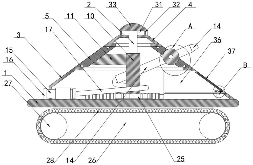
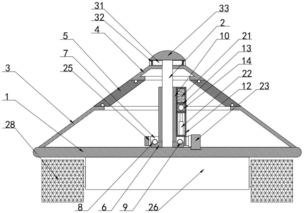
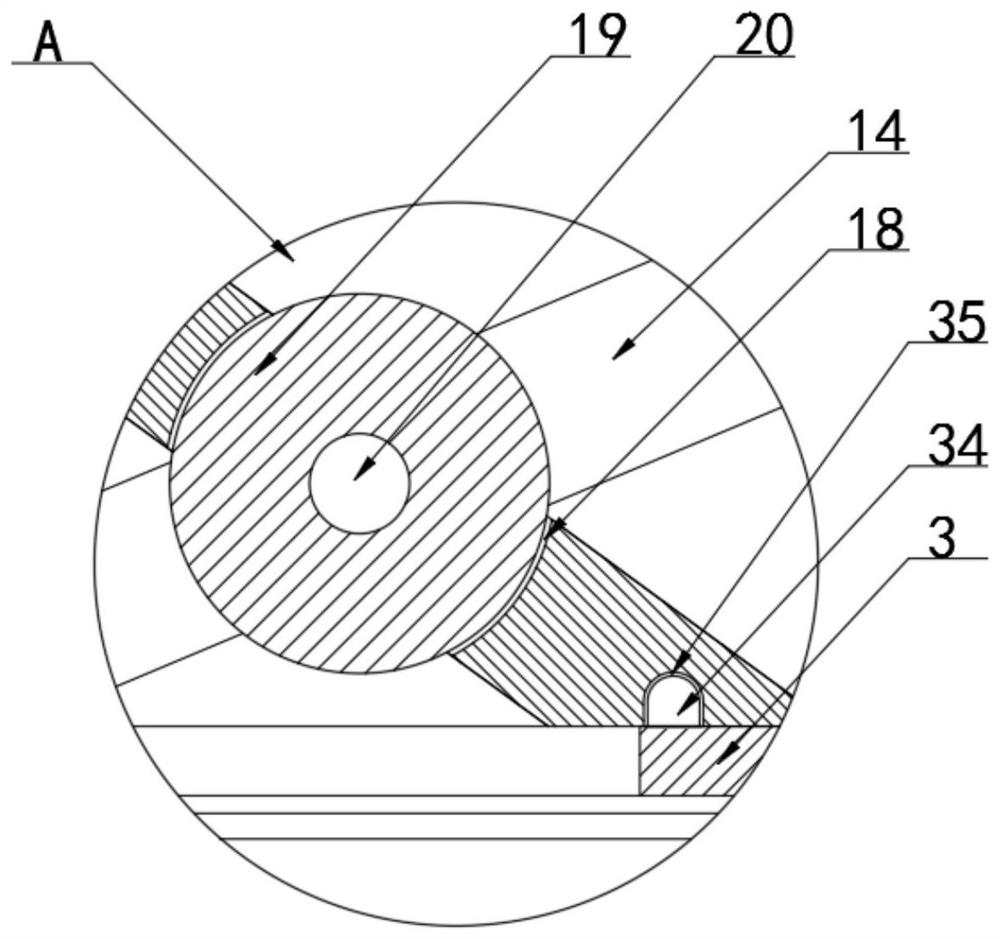
[0027] according to Figure 1-4 The shown robot for fire rescue includes a workbench 1, the top of the workbench 1 is provided with a support column 2, and the periphery of the top of the workbench 1 is provided with a first shell 3, and the top surface of the support column 2 is A second housing 4 is provided, a rotating housing 5 is provided between the first housing 3 and the second housing 4, a fixing seat 6 is provided at the bottom of the support column 2, and a rotating seat 7 is provided at the top of the fixing seat 6, Both the top surface of the fixed seat 6 and the bottom surface of the rotating seat 7 are provided with a groove 8, the inside of the groove 8 is provided with a steel ball 9, the top of the rotating seat 7 is provided with a rotating cylinder 10, and the rotating cylinder 10 is connected to the rotating cylinder. A connecting plate 11 is arranged between the inner walls of the housing 5, and a fixed frame 12 is arranged on one side of the surface of t...

Embodiment 2

[0030] according to Figure 1-2As shown in a robot for fire rescue, the bottom of the workbench 1 is provided with a chassis 26, and both ends of the chassis 26 are provided with rollers 27, and a crawler belt 28 is provided between the two rollers 27. The power unit inside the 26 controls the rotation of the rollers 27, and cooperates with the crawler belt 28 between the rollers 27 to realize the movement of the robot in the fire field;

[0031] according to Figure 5 As shown in a robot for fire rescue, the two sides of the top of the second housing 4, the front side and the rear side are all provided with partition plates 29, and a mounting seat 30 is provided between the two partition plates 29 A camera 31 is arranged inside the installation seat 30, a glass cover 32 is arranged outside the camera 31, a protective cover 33 is arranged on the top of the support column 2, and the top of the second housing 4 is divided into four parts by a partition plate 29. The fan shape ...


PUM


Abstract

The invention discloses a robot for fire rescue. The robot for fire rescue is characterized in that the robot comprises a workbench; a support column is disposed on top of the workbench; a first shellis disposed on the periphery of the top of the workbench; a second shell is arranged on the surface of the top of the support column; a rotating shell is arranged between the first shell and the second shell; a fixed seat is disposed at the bottom of the support column; a rotating seat is disposed on top of the fixed seat; grooves internally provided with steel balls are arranged on the surface of the top of the fixed seat and the surface of the bottom of the rotating seat; a rotating cylinder is disposed on top of the rotating seat; a connecting plate is arranged between the rotating cylinder and the inner wall of the rotating shell. With the arrangement of a rotating cylinder, a fixing frame, a slider, a water spray gun, a rotating disc, a first spring, a first electric push rod, a rack, a second electric push rod and a ring gear, the robot for the fire rescue has the advantages of facilitating precise control of fire extinguishing of fire sources by the water spray gun carried by arobot, improving accuracy of operation, improving fire extinguishing efficiency and protecting personal safety of firefighters.

Description

technical field [0001] The invention relates to the technical field of robots, in particular to a robot for fire-fighting and rescue. Background technique [0002] Natural disasters are abnormal phenomena that occur in the natural world that human beings rely on. The harm caused by natural disasters to human society is often shocking. Among them, there are sudden disasters such as earthquakes, volcanic eruptions, mudslides, tsunamis, typhoons, floods, etc.; when a fire breaks out in a modern building, firefighters cannot enter the room to extinguish the fire because the room is full of unknown toxic gases and thick smoke. Accurately extinguishing the indoor fire source affects the rescue time and seriously threatens personal safety and property safety. [0003] Therefore, it is necessary to invent a kind of robot for fire rescue to solve the above problems. Contents of the invention [0004] The purpose of the present invention is to provide a kind of robot that is used ...

Claims


Application Information

Patent Timeline
Patent Type & Authority Patents(China)
IPC IPC(8): A62C27/00A62C37/00
CPCA62C27/00A62C37/00
Inventor 陈杰
Owner 天长市安康消防设备有限公司
Learn More