Supercharge Your Innovation With Domain-Expert AI Agents!

Air compressor casting welding bracket

A technology for welding brackets and air compressors, applied in welding equipment, auxiliary welding equipment, welding/cutting auxiliary equipment, etc., can solve the problems that welding brackets cannot meet the needs of production and employees, and achieve the effect of facilitating welding work

Active Publication Date: 2019-01-04
WUHU FUMA AUTO SPARE PARTS
View PDF6 Cites 0 Cited by
  • Summary
  • Abstract
  • Description
  • Claims
  • Application Information

AI Technical Summary

Problems solved by technology

[0003] Aiming at the deficiencies of the prior art, the present invention provides an air compressor casting welding bracket, which solves the problem that the currently used welding bracket cannot meet the needs of production and employees. The present invention adopts the following technical solutions to solve the technical problem: including the base With the two brackets located on the base, rotating shafts are worn on the top of the two brackets, and a clamping bracket is provided between the two rotating shafts. One cylinder, the first connecting rod is connected with the first connecting rod, the other end of the first connecting rod is connected with the clamping device, two second cylinders are arranged on the top of the left and right ends of the clamping bracket, and the two second cylinders are respectively located Above and below the first cylinder, a second connecting rod is connected to the second cylinder, the other end of the second connecting rod passes through the clamping device and extends to the inside of the clamping device, and the other end of the second connecting rod is connected with a telescopic rod

Method used


Image

  • Air compressor casting welding bracket

Examples


Embodiment Construction

[0010] In order to deepen the understanding of the present invention, the present invention will be further described below in conjunction with the examples, which are only used to explain the present invention, and do not constitute a limitation to the protection scope of the present invention.

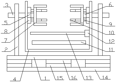
[0011] Such as figure 1 As shown, the present embodiment provides an air compressor casting welding bracket, including a base 1 and two brackets 2 located on the base 1, the tops of the two brackets 2 are pierced with rotating shafts 3, and the two rotating shafts 3 are provided with There is a clamping bracket 4, and the clamping bracket 4 is a flat structure, and the tops of the left and right ends of the clamping bracket 4 are provided with a first cylinder 5, and the first cylinder 5 is connected with a first connecting rod 6, and the first connecting rod 6 The other end is connected with a clamping device 7, through which the casting is fixed above the clamping bracket to facili...


PUM


Abstract

The invention provides an air compressor casting welding bracket. The air compressor casting welding bracket comprises a base and two supports located on the base, rotating shafts penetrate through the top ends of the two supports, a clamping support is arranged between the two rotating shafts, the clamping support is of a similar-u structure, first cylinders are arranged at the top ends of the left and right ends of the clamping support, first connecting rods are connected to the first cylinders, the other end of each first connecting rod is connected with a clamping device, the top ends of the left and right ends of the clamping support are each provided with two second cylinders, every two corresponding second cylinders are located above and below the corresponding first cylinder, second connecting rods are connected to the second cylinders, the other ends of the second connecting rods penetrate through the clamping device to extend to the interior of the clamping device, and the other ends of the second connecting rods are connected with telescopic rods. According to the air compressor casting welding bracket, the second connecting rods are driven by the second cylinders, so that the telescopic rods are inserted into perforated holes of castings, meanwhile, the first cylinder drives the clamping device to be away from the casting, the outer surface of the casting is completely exposed, and the welding work is facilitated.

Description

technical field [0001] The invention relates to the field of air compressors, in particular to an air compressor casting welding bracket. Background technique [0002] The welding process is required in the production of automobile air compressors. During the welding process, the castings need to be clamped. For the castings with large welding surfaces, they need to be welded in stages to avoid missing welding at the clamping places. If the castings are designed When there is a perforation, it is only necessary to pass the tool through the perforation to fix the casting. However, in the current production, there is no device that meets this condition, and the casting can only be clamped several times before welding. When the production volume of the air compressor When it is old, the work intensity of the staff increases, and the body is prone to fatigue. Therefore, it is very necessary to solve such problems. Contents of the invention [0003] Aiming at the deficiencies ...

Claims


Application Information

Patent Timeline
IPC IPC(8): B23K37/04B23K37/047
CPCB23K37/0426B23K37/047
Inventor 汪大高秦其斌刘怀舟
Owner WUHU FUMA AUTO SPARE PARTS
Features
  • R&D
  • Intellectual Property
  • Life Sciences
  • Materials
  • Tech Scout
  • Unparalleled Data Quality
  • Higher Quality Content
  • 60% Fewer Hallucinations
Learn More