Reversible welding clamp

A welding jig and flip jig technology, applied in welding equipment, auxiliary welding equipment, welding/cutting auxiliary equipment, etc., can solve the problems of a large number of production personnel, a lot of time-consuming, and an increase in production costs.

Inactive Publication Date: 2018-12-04
TECH TRANSFER CENT CO LTD NANJING UNIV OF SCI & TECH
View PDF6 Cites 6 Cited by
  • Summary
  • Abstract
  • Description
  • Claims
  • Application Information

AI Technical Summary

Problems solved by technology

This kind of welding fixture is usually limited by the design, resulting in too much time-consuming in the process of picking and placing parts, which seriously affects the production cycle, and the operation process is complicated, requiring a large number of fixtures and production personnel, which increases a lot of production costs.

Method used


Image

  • Reversible welding clamp
  • Reversible welding clamp
  • Reversible welding clamp

Examples


Embodiment Construction

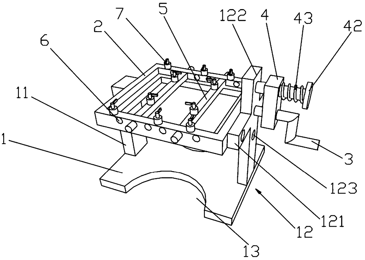
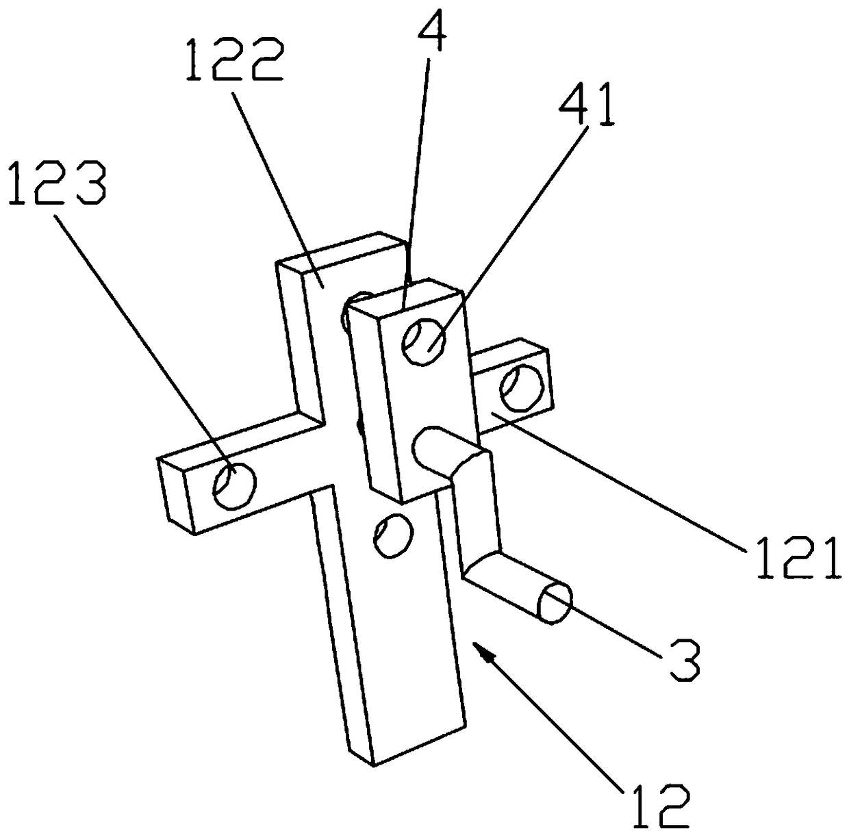
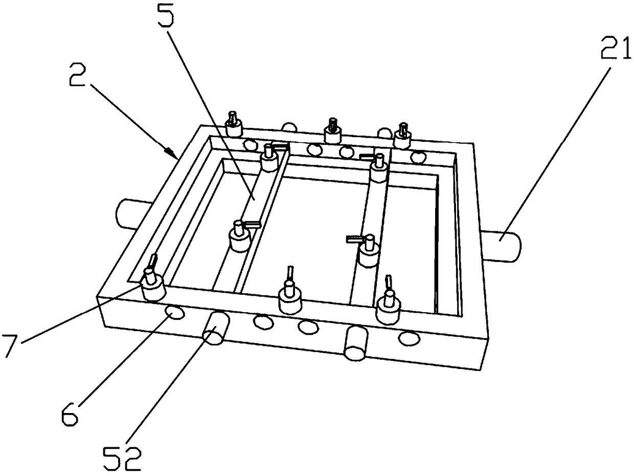
[0020] The specific embodiments of the present invention will be described below with reference to the accompanying drawings.

[0021] like Figure 1-5 As shown, a reversible welding fixture of this embodiment includes a fixture base plate base 1, and two ends of the clamp base plate base 1 are respectively provided with a first support column 11 and a second support column 12. One end and one end of the second support column 12 are vertically arranged on the fixture base plate 1, and a rectangular frame flipping fixture plate 2 is movably arranged between the other end of the first support column 11 and the other end of the second support column 12. The rectangular frame A plurality of fixing rods 5 parallel to each other are also movably arranged in the overturning fixture plate 2, the fixing rods 5 are rectangular rods, and a plurality of clamping cylinders 7 are also arranged on the rectangular frame overturning fixture plate 2 and the fixing rods 5, and the rectangular fr...


PUM


Abstract

The invention provides a reversible welding clamp and relates to the technical field of welding clamps. The reversible welding clamp comprises a clamp bottom plate seat. A first supporting column anda second supporting column are separately arranged at two ends of the clamp bottom plate seat; one end of the first supporting column and one end of the second supporting column are arranged on the clamp bottom plate seat; a rectangular frame reversing clamp plate is movably arranged between the other end of the first supporting column and the other end of the supporting column; a plurality of parallel fixed bars are also movably arrange in the rectangular frame reversing clamp plate; the fixed bars are rectangular bars; a plurality of clamping air cylinders are also arranged on the rectangular frame reversing clamp plate and the fixed bars; rotary shafts are also separately arranged at two ends of the rectangular frame reversing clamp plate; and the reversing clamp plate is rotatably arranged between the other end of the first supporting column and the other end of the supporting column. The reversible welding clamp provided by the invention has the advantages of welding multiple faces of a product only by reversing the rectangular frame reversing clamp plate and the like.

Description

technical field [0001] The invention relates to the technical field of welding fixtures, in particular to a reversible welding fixture. Background technique [0002] At present, welding of parts is usually carried out on welding jigs. Usually, the parts are placed on the welding fixture, positioned through the positioning holes, and then fixed by pressing the surface of the parts with a pressing mechanism, and then welded. However, in the actual welding process, some parts need to be welded on two or more sides, especially the base plate parts are relatively large. In this case, the parts need to be removed after the welding on one side is completed, and then placed on another fixture for welding. This kind of welding fixture is usually limited by design, which results in excessive time-consuming in the process of picking and placing parts, which seriously affects the production cycle, and the operation process is complicated. The number of fixtures required and the number ...

Claims


Application Information

Patent Timeline
Patent Type & Authority Applications(China)
IPC IPC(8): B23K37/047
CPCB23K37/047
Inventor 孙伟明吕大为
Owner TECH TRANSFER CENT CO LTD NANJING UNIV OF SCI & TECH
Why Eureka
Try Eureka