Threaded block disassembling device

A technology for dismantling devices and threaded blocks, which is applied in the field of plastic production equipment, can solve the problems of high equipment cost and complex structure, and achieve the effect of low equipment cost and compact structure

Pending Publication Date: 2019-01-04
张德修
View PDF1 Cites 2 Cited by
  • Summary
  • Abstract
  • Description
  • Claims
  • Application Information

AI Technical Summary

Problems solved by technology

There are many kinds of threaded block removal devices in the prior art, such as the screw threaded element removal device disclosed in the Chinese invention patent application (application number 201610739241.7) on January 4, 2017. The technical solution of this patent application uses a screw ferrule to fix the threaded block , through two sets of hydraulic cylinders to drive the base to move and disassemble the lower threaded block; the disadvantage of this equipment is that it needs to use two sets of hydraulic cylinders to drive, resulting in complex structure and high equipment cost

Method used


Image

  • Threaded block disassembling device
  • Threaded block disassembling device
  • Threaded block disassembling device

Examples


Embodiment 1

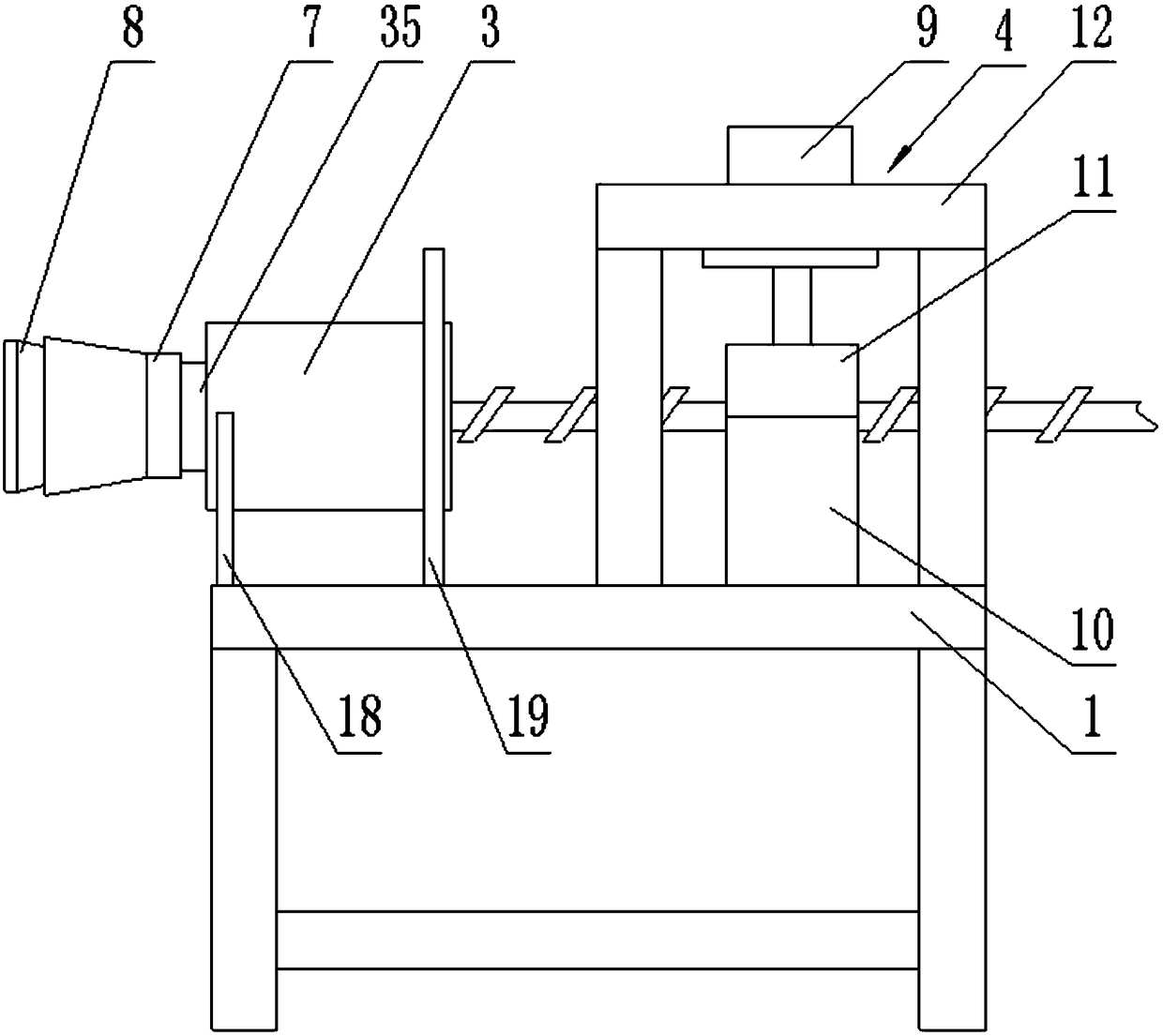
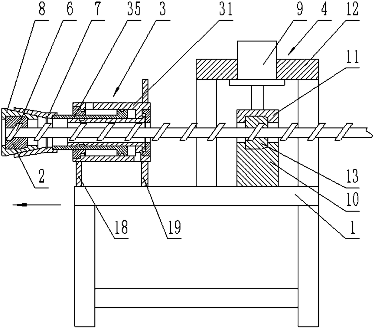
[0044] like Figure 1-4 A threaded block removal device shown includes a support base 1, a hollow hydraulic cylinder 3 and a mandrel clamping mechanism 4. On the upper surface of the support base 1, a first support frame 18, a second support frame 18, and a second Support frame 19 and hydraulic cylinder support frame 12. The upper end of the first support frame 18 is provided with semicircular groove, and this semicircular groove is used for installing hollow hydraulic cylinder 3, offers the hole that is used to install hollow hydraulic cylinder 3 in the middle part of second support frame 19, and hollow hydraulic cylinder 3 The left end is installed on the semicircular groove (the hollow hydraulic cylinder 3 can also be welded on the semicircular groove), and the right end of the hollow hydraulic cylinder 3 passes through the hole on the second support frame 19 and is welded on the second support frame 19 . The hollow hydraulic cylinder 3 is an existing technology, such as ...

Embodiment 2

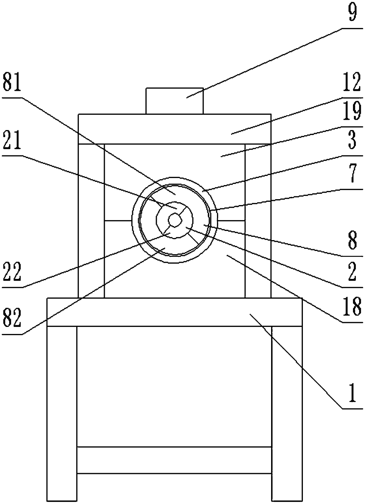
[0049] like Figure 11 Shown, embodiment 2 is improved on the basis of embodiment 1. The outer tapered sleeve 8 in Embodiment 2 has an integral structure (that is, the upper outer tapered sleeve 81 and the lower outer tapered sleeve 82 in Embodiment 1 are fixedly connected to each other). With such a structure, after putting the outer tapered sleeve 8 on the first screw ferrule 2, it can prevent the first upper threaded clip 21 from being separated from the first lower threaded clip 22, but it is inconvenient to install.

[0050] The rest of the structure and working principle of embodiment 2 are the same as embodiment 1.

Embodiment 3

[0052] like Figure 12-13 As shown, Embodiment 3 is changed on the basis of the structure of the thread block removal device in Embodiment 1. The large end of the outer tapered sleeve 8 in embodiment 3 is threadedly connected to the left end of the piston cylinder 35, and the mandrel clamping member is replaced by the first V-shaped block 16 and the second V-shaped block 17 in the embodiment 3. The V-shaped surfaces of a V-shaped block 16 and the second V-shaped block 17 are all towards the mandrel 5, and the first V-shaped block 16 is fixedly connected on the second clamping seat 11, and the second V-shaped block 17 is fixedly connected on the first On the clamping seat 10.

[0053] In Embodiment 1, the threaded block removal device disassembles the threaded block 6 from one end of the mandrel 5. When the last few threaded blocks 6 are disassembled, because the length of the last few threaded blocks 6 is not enough to be clamped by the first hydraulic cylinder 9, that is, U...


PUM


Abstract

The invention discloses a threaded block disassembling device which comprises a support base and a first screw rod clamp sleeve, wherein a hollow hydraulic cylinder and a mandrel clamping mechanism are mounted on the support base; the hollow hydraulic cylinder is arranged on a mandrel in a sleeving manner; the diameter of the inner hole of the body of the hollow hydraulic cylinder is greater thanthe diameter of a threaded block; the piston cylinder of the hollow hydraulic cylinder is detachably connected with an inner conical sleeve; the inner conical sleeve is internally provided with an outer conical sleeve; the inner conical surface of the inner conical sleeve is connected with the outer conical surface of the outer conical sleeve; the screw rod clamp sleeve is clamped inside the outerconical sleeve. Disassembling operation can be completed by using one hydraulic cylinder, and the threaded block disassembling device is compact in structure and low in equipment cost.

Description

technical field [0001] The invention belongs to the technical field of plastic production equipment, in particular to a thread block dismounting device. Background technique [0002] The screw of the twin-screw extruder adopts a building block design, and various thread blocks (thread elements) are installed on the mandrel through splines. Due to damage to the threaded block or different processes, it is often necessary to disassemble the threaded block from the mandrel, and replace or reassemble the threaded block. There are many kinds of threaded block removal devices in the prior art, such as the screw threaded element removal device disclosed in the Chinese invention patent application (application number 201610739241.7) on January 4, 2017. The technical solution of this patent application uses a screw ferrule to fix the threaded block , through two groups of hydraulic cylinders to drive the base to move and disassemble the lower threaded block; the disadvantage of this...

Claims


Application Information

Patent Timeline
Patent Type & Authority Applications(China)
IPC IPC(8): B29C48/25
Inventor 张德修
Owner 张德修
Why Eureka
Try Eureka