
Multifunctional dyeing machine

A cloth dyeing machine and multifunctional technology, applied in the field of textile printing and dyeing, can solve the problems of easily soiling clothes, affecting the quality of cloth, low efficiency, etc., and achieve the effects of speeding up the drying speed, saving the dyeing time, and increasing the output.

Active Publication Date: 2020-11-27
浙江乐筑纺织科技有限公司
View PDF6 Cites 0 Cited by
  • Summary
  • Abstract
  • Description
  • Claims
  • Application Information

AI Technical Summary

Problems solved by technology

[0003] In the process of dyeing cloth, the traditional method is to manually put the cloth into the dye vat, and then manually drag the other end of the cloth to slowly drag for dip-dyeing. People directly contact with the dye, which is easy to stain the clothes. The dye contains many harmful substances. , it is easy to damage the health of the workers, and the manual operation cannot uniformly control the time of dipping. Due to the inconsistent speed of different workers, the quality of the dip-dyed cloth is not the same, and the dip-dyeing is uneven, which affects the quality of the whole batch of cloth. To dry the impregnated cloth, the traditional method is to infect first, and then dry the cloth. The infestation and drying are carried out separately, which is time-consuming, laborious, and inefficient. In addition, the original drying method is usually oven-dried, which has poor safety. Ineffective

Method used


Image

  • Multifunctional dyeing machine
  • Multifunctional dyeing machine
  • Multifunctional dyeing machine

Examples


Embodiment 1

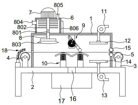
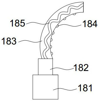
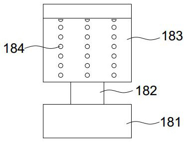
[0026] Such as Figure 1-5As shown, the solution adopted by the present invention to solve the above-mentioned technical problems is: a multi-functional cloth dyeing machine, including a housing 1 positioned on the upper surface of the frame 2, the bottom of the housing 1 is provided with a sewage outlet 16, and the sewage outlet 16 is connected to the bottom of the machine. The sewage collection box 17 below the frame 2 is connected, the top of the housing 1 is provided with a dye tank 6, the left and right sides of the housing 1 are provided with support bases 3, and the support bases 3 are respectively equipped with first cloth rolls that are movably connected by rollers. 4 and the second cloth rolling roller 5, the inner walls on both sides of the housing 1 are provided with slots for cloth to pass through, and the first cloth rolling roller 4 is provided with a preheating mechanism 18 on one side, and the preheating mechanism 18 includes an air pump 181, The air outlet pi...

Embodiment 2

[0028] Such as figure 1 As shown, the optimization scheme of this embodiment on the basis of Embodiment 1 is: a rotating motor 7 is arranged above the dye tank 6, and the output end of the rotating motor 7 passes through the dye tank 6 to be connected to a discharge pipe 8, and the discharge pipe 8 Stirring rods 802 are evenly distributed on the top, driven by the rotating motor 7 to drive the stirring rods 802 to rotate, the dye and clear water can be stirred evenly, and then the dyeing of the cloth can be dyed more evenly when the dye is dyed, and the color depth of the dyed cloth can be avoided. The first situation improves the quality of the dyed cloth. The discharge pipe 8 below the stirring rod 802 is provided with a through hole 801. The discharge pipe 8 is movably connected with the housing 1, and the discharge pipe 8 in the housing 1 The end is connected with a nozzle 803, and the uniformly stirred dye enters the inside of the discharge pipe 8 through the through hole...

Embodiment 3

[0030] Such as figure 1 , 6 , 7, and 8, the optimization scheme of this embodiment on the basis of Embodiment 1 is: the top of the housing 1 is provided with a swing device 9, the swing device 9 includes a support plate 901, and the support plate 901 is movable through a fixed rod 905 A swing rod 904 is connected, and a bar-shaped hole 906 is opened on the swing rod 904. A cylinder 908 is arranged at the bottom of the swing rod 904. A disc 902 is movably connected between the swing rod 904 and the support plate 901 through an axis column 903. 902 is driven and rotated by the motor 909 on the back of the support plate 901, the disc is provided with a fixed block 907, and the fixed block 907 is connected with the strip hole 906, and the inner bottom of the housing 1 is provided with an elastic seat 10, which includes a base 101 , the base 101 is provided with a spring 102, the spring 102 is provided with an arc-shaped block 103, and the arc-shaped block 103 is provided with a p...


PUM


Abstract

The invention discloses a multifunctional dyeing machine. The dyeing machine comprises a shell located on the upper surface of a frame. The bottom of the shell is provided with a sewage draining exit.The sewage draining exit is connected to a sewage collecting box located below the frame. A dye box is arranged above the shell. The left and right sides of the shell are provided with support seats.The support seats are provided with a first cloth roller and a second cloth roller which are movably connected through a roller. The inner walls of the two sides of the shell are provided with grooveholes through which cloth can pass. One side of the first cloth roller is provided with a preheating mechanism. The preheating mechanism comprises an air pump. An exit pipe above the air pump is connected to a heating cover. An s-shaped heating pipe is arranged in the heating cover. The corresponding cover of the heating cover is arranged on the external portion of the first cloth roller. The inner arc surface of the heating cover is uniformly distributed with blowholes. By using the device, people do not need to directly touch dyed cloth, worker health can be effectively protected, and the cloth can be preheated, cloth dyeing and drying are integrated into one body, dyeing is uniform and the quality of the dyed cloth is high.

Description

technical field [0001] The invention belongs to the technical field of textile printing and dyeing, and in particular relates to a multifunctional cloth dyeing machine. Background technique [0002] Printing and dyeing is also called dyeing and finishing. It is a processing method, and it is also a general term for pretreatment, dyeing, printing, finishing, washing, etc.; the undergraduate dyeing and finishing major has now been incorporated into the light chemical engineering major; as early as the Neolithic Age six or seven thousand years ago, Our ancestors were able to dye sackcloth red with hematite powder. The primitive tribes living in the Nomuhong area of ​​the Qaidam Basin in Qinghai can dye wool into yellow, red, brown, blue and other colors, and weave woolen cloth with colored stripes. During the Shang and Zhou dynasties, dyeing technology continued to improve. [0003] In the process of dyeing cloth, the traditional method is to manually put the cloth into the ...

Claims


Application Information

Patent Timeline
Patent Type & Authority Patents(China)
IPC IPC(8): D06B3/10D06B15/09D06B23/04D06B23/20D06B23/22
CPCD06B3/10D06B15/09D06B23/04D06B23/205D06B23/22
Inventor 李佳莘
Owner 浙江乐筑纺织科技有限公司
Learn More