

Textile cloth printing and dyeing drying device
A drying device and a technology for textile cloth, applied in the field of textile processing, can solve problems such as poor drying effect of textile cloth, and achieve the effects of ensuring uniformity, good drying effect and uniform drying.
Active Publication Date: 2019-01-04
重庆博工商贸有限责任公司
View PDF4 Cites 4 Cited by
- Summary
- Abstract
- Description
- Claims
- Application Information
AI Technical Summary
Problems solved by technology
[0003] The purpose of the present invention is to provide a textile cloth printing and dyeing drying device to solve the problem of poor drying effect of textile cloth
Method used
View moreImage
Smart ImageViewing Examples

Examples
Embodiment Construction
[0015] The present invention will be described in further detail below by means of specific embodiments:
Login to View More PUM
 Abstract
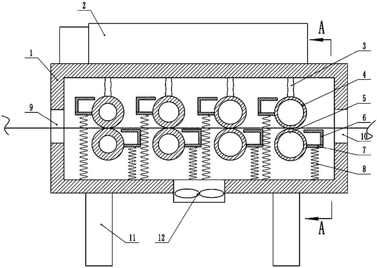
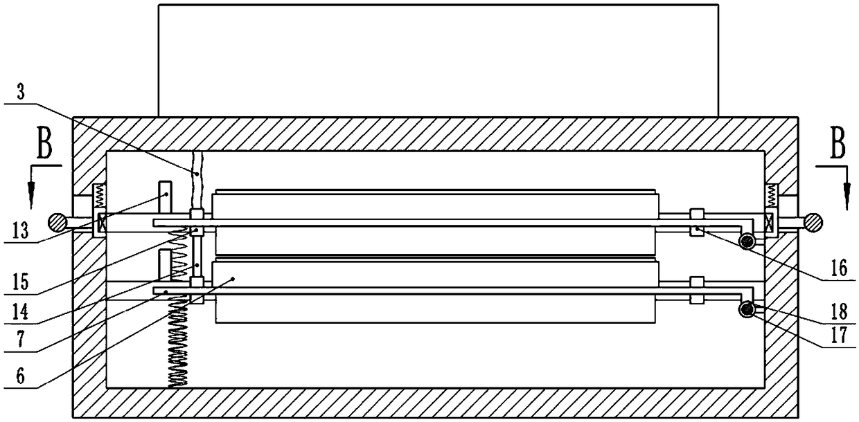
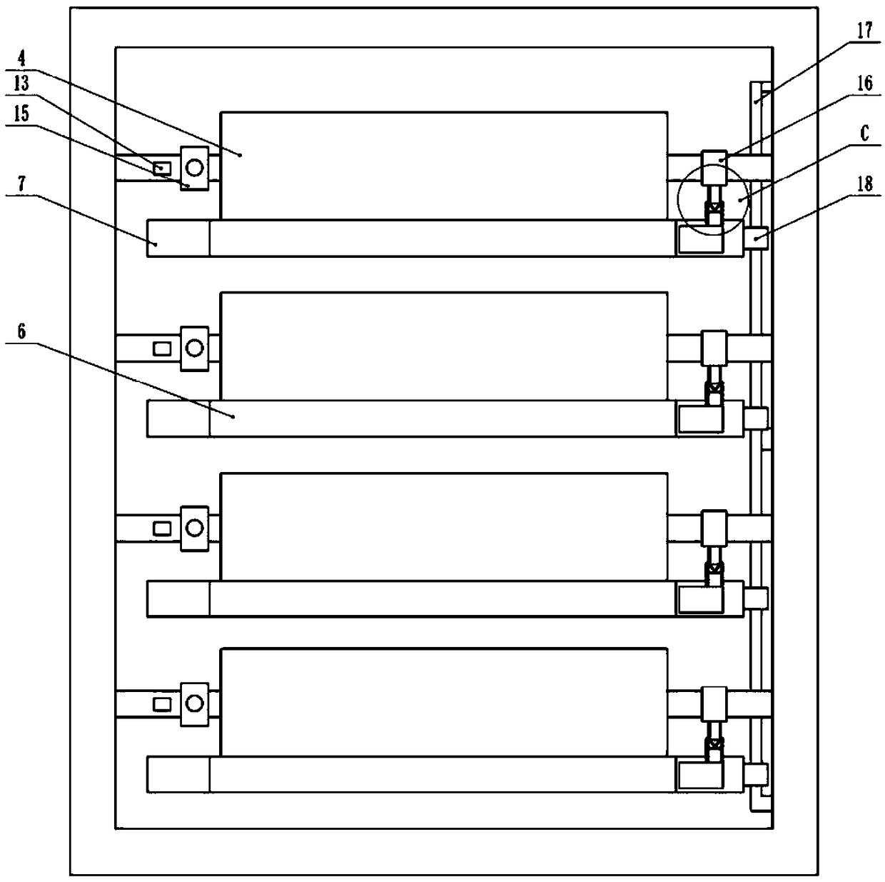
The invention belongs to the textile processing technology field and especially discloses a textile cloth printing and dyeing drying device. The device comprises a drying box. The two ends of the drying box are provided with a feed inlet and a discharge port. Several drying roller groups are arranged in the drying box. Each drying roller group comprises a moving roller and a fixing roller which directly and vertically face each other. The moving roller and the fixing roller are rotatably installed in the drying box. The drying box is provided with a lifting mechanism used for driving the moving roller to rise and fall. Heat conduction chambers are arranged in the moving roller and the fixing roller. The wall thicknesses of the moving roller and the fixing roller are gradually reduced alonga direction from the feed inlet to the discharge port. Several material scrape plates which are contacted with the moving roller or the fixing roller are arranged in the drying box. One end of each material scrape plate is rotatably connected to the drying box. A pressing spring is connected between the other end of each material scrape plate and the bottom wall of the drying box. The moving roller and the fixing roller are provided with pressing rods capable of pressing down the material scrape plates. In the scheme, the moving roller and the fixing roller with different wall thicknesses arearranged, the stepwise drying of a textile fabric is realized and a drying effect is good.
Description
technical field [0001] The invention belongs to the technical field of textile processing, and in particular relates to a drying device for textile cloth printing and dyeing. Background technique [0002] Cloth drying is a process that must be passed through in the textile industry. The existing dryers generally support the cloth through the box through rotating rollers, and heat it through the heating tube in the box to dry it. The tube is generally above or below the fabric, and the inside of the box is formed into a high-temperature and dry environment through the heating tube to realize the drying treatment of the fabric. However, if the distance between the heating tube and the fabric is too large, it is easy to make the fabric dry unevenly, and During the drying process, the temperature in the box is basically constant, so the drying temperature of the cloth from entering the box to going out of the box is constant, so that there is no transition in the drying process ...
Claims
Login to View More Application Information
Patent Timeline
 Patent Type & Authority Applications(China)
IPC IPC(8): D06B15/09D06B23/20
CPCD06B15/09D06B23/20
Inventor 孙敏
Owner 重庆博工商贸有限责任公司