Sealing waterproof mechanism used in power distribution cabinet

A technology for power distribution cabinets and sealing rubber rings, which is applied in the substation/power distribution device shell, substation/switchgear cooling/ventilation, electrical components, etc., which can solve the problems of electrical equipment not working normally, easy aging, equipment corrosion aging, etc. question

Inactive Publication Date: 2020-06-19
朱小飞
View PDF6 Cites 3 Cited by
  • Summary
  • Abstract
  • Description
  • Claims
  • Application Information

AI Technical Summary

Problems solved by technology

[0002] The power distribution cabinet is a commonly used power distribution equipment. It is often placed in the open air, so it is easy to enter the power distribution cabinet in rainy weather, which will affect the stability and safety of the communication cabinet. The existing technology mainly uses The sealing strip is used for sealing. Although it can complete the rainwater seal to a certain extent, it is easy to age in the harsh environment after long-term use, thus affecting the waterproof performance of normal use, and the applicability and practicability are limited.
In the case of flooding, water will enter the interior of the power distribution cabinet from the gap in the shell of the power distribution cabinet, and the components in the power distribution cabinet will be soaked in water, which will cause the electric

Method used


Image

  • Sealing waterproof mechanism used in power distribution cabinet
  • Sealing waterproof mechanism used in power distribution cabinet
  • Sealing waterproof mechanism used in power distribution cabinet

Examples


Embodiment Construction

[0021] The following will clearly and completely describe the technical solutions in the embodiments of the present invention with reference to the accompanying drawings in the embodiments of the present invention. Obviously, the described embodiments are only some, not all, embodiments of the present invention. Based on the embodiments of the present invention, all other embodiments obtained by persons of ordinary skill in the art without making creative efforts belong to the protection scope of the present invention.

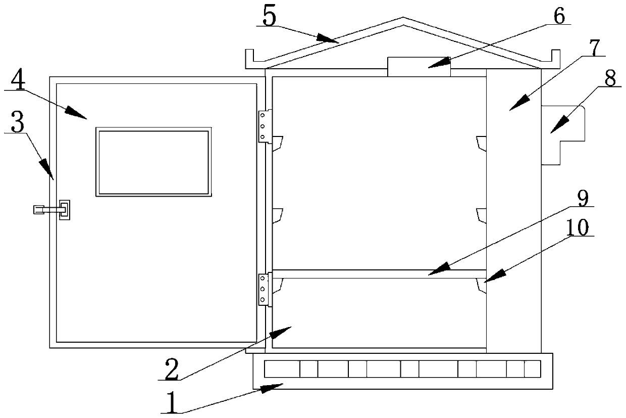
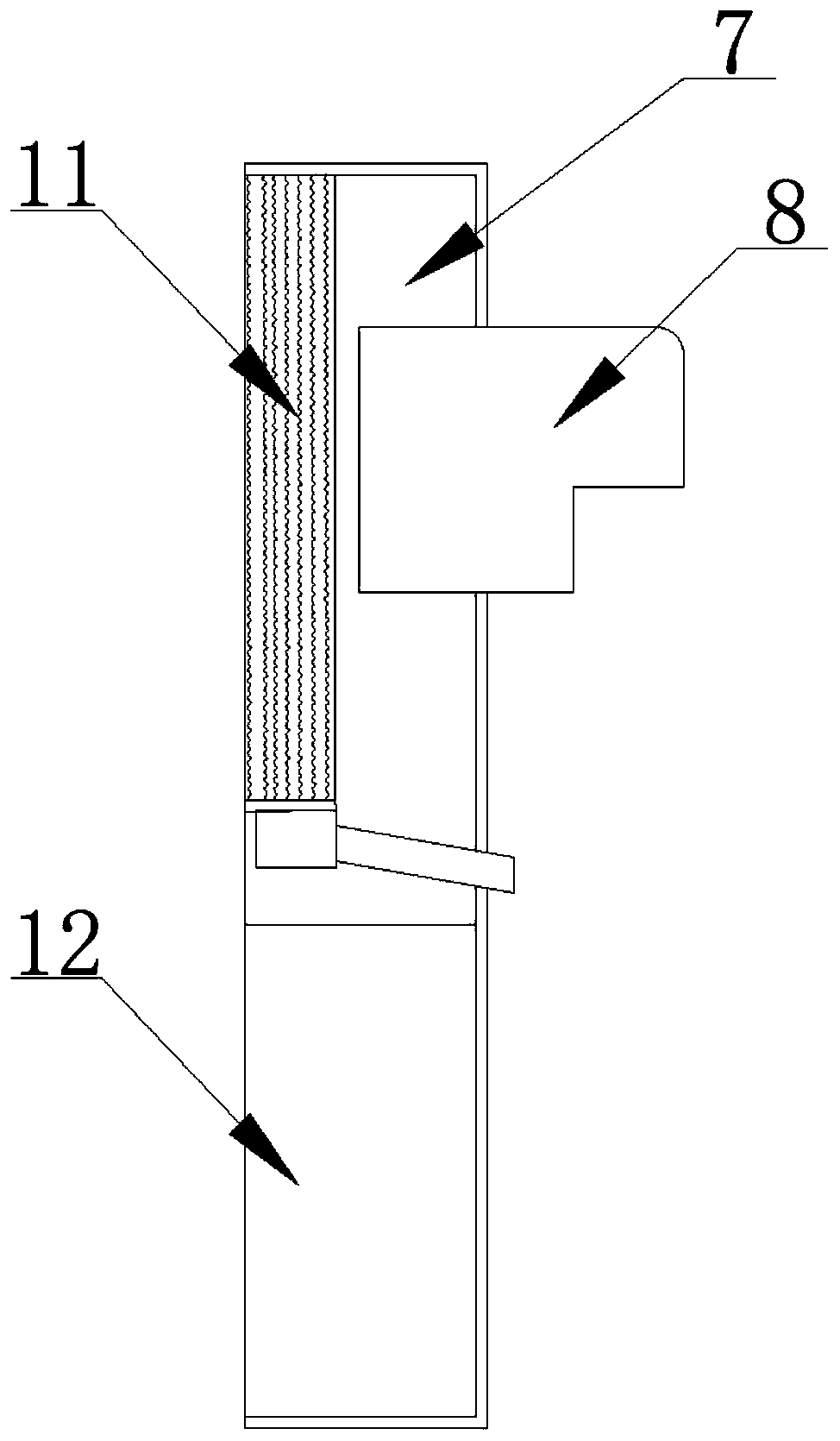
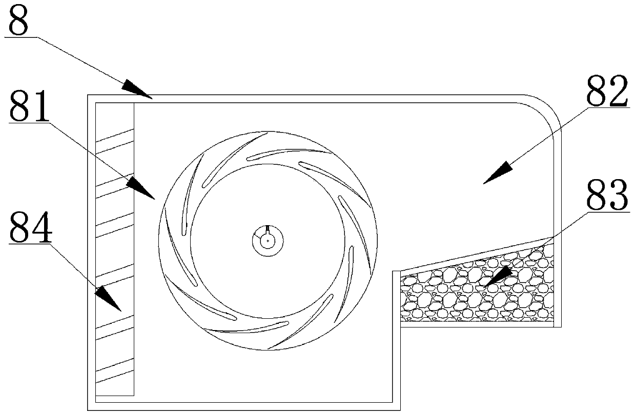
[0022] as attached Figure 1-4 The sealing and waterproof mechanism for the interior of the power distribution cabinet shown includes a hydrophobic base 1, the top surface of the hydrophobic base 1 is fixedly welded with a main body 2 of the power distribution cabinet, and one side of the main body 2 of the power distribution cabinet is twisted and connected with a sealed cabinet door 4. A sealing rubber ring 3 is attached to the edge of the door 4 of the seal...


PUM


Abstract

The invention discloses a sealing waterproof mechanism used in a power distribution cabinet, and specifically relates to the field of power distribution cabinets. The sealing waterproof mechanism comprises a drainage base and a power distribution cabinet body; an electrostatic dehumidification box is arranged on the inner side of the power distribution cabinet body; the inner wall of the power distribution cabinet body and the inner side of an air inlet cooling mechanism are provided with a plurality of fixed support bars and equipment mounting racks; an electrostatic grid and a high-voltage electrostatic generator are arranged in the electrostatic dehumidification box; the top surface of the inner cavity of the power distribution cabinet body is provided with a temperature and humidity sensor; and one side of the electrostatic dehumidification box is provided with the air inlet cooling mechanism. According to the invention, the electrostatic grid in the electrostatic dehumidificationbox is used for filtering airflow entering the power distribution cabinet; liquid drop small particles and part of dust particles mixed in a large amount of inlet air flow can be effectively adsorbedthrough the electrostatic adsorption effect; the liquid drop small particles are gathered and liquefied in the electrostatic grid and then collected and discharged out of the outer side of the power distribution cabinet; and the dry environment in the power distribution cabinet is guaranteed on the basis that the sealing performance of the power distribution cabinet is not damaged.

Description

technical field [0001] The invention relates to the technical field of power distribution cabinets, and more specifically, the invention is a sealing and waterproof mechanism for the interior of a power distribution cabinet. Background technique [0002] The power distribution cabinet is a commonly used power distribution equipment. It is often placed in the open air, so it is easy to enter the power distribution cabinet in rainy weather, which will affect the stability and safety of the communication cabinet. The existing technology mainly uses The sealing strip is sealed. Although it can complete the rainwater seal to a certain extent, it is easily aged in harsh environments for a long time, thereby affecting the waterproof performance of normal use, and the applicability and practicability are limited. In the case of flooding, water will enter the interior of the power distribution cabinet from the gap in the shell of the power distribution cabinet, and the components in ...

Claims


Application Information

Patent Timeline
IPC IPC(8): H02B1/30H02B1/28H02B1/56
CPCH02B1/28H02B1/30H02B1/565
Inventor 朱小飞周迪
Owner 朱小飞
Why Eureka
Try Eureka