Connection structure of network cable joints

A network cable connector and connection structure technology, which is applied in the direction of connection, two-part connection device, and components of the connection device, etc., can solve the problem of not setting network cable connectors for heat dissipation, dust-proof and moisture-proof accessories, no rotation and easy connection, and structural design. Unreasonable and other problems, to avoid poor contact, low manufacturing cost, and reasonable design

Inactive Publication Date: 2019-06-25
胡学朋
View PDF1 Cites 3 Cited by
  • Summary
  • Abstract
  • Description
  • Claims
  • Application Information

AI Technical Summary

Problems solved by technology

It has two kinds of STP and UTP. We commonly use UTP. The existing network cable connectors are dazzling. Difficult to install, thus bringing certain inconvenience to the user, so a connection structure of network cable connector is set up to solve the inconvenience of people in use, such as the design with the publication number CN104600509A, which does not have rotation and is easy to connect function, and there is no heat dissipation, dust-proof and moisture-proof accessories for the network cable connector, so it cannot solve people's problems in the use of network cables

Method used


Image

  • Connection structure of network cable joints
  • Connection structure of network cable joints

Examples


Embodiment Construction

[0017] The following will clearly and completely describe the technical solutions in the embodiments of the present invention with reference to the accompanying drawings in the embodiments of the present invention. Obviously, the described embodiments are only some, not all, embodiments of the present invention.

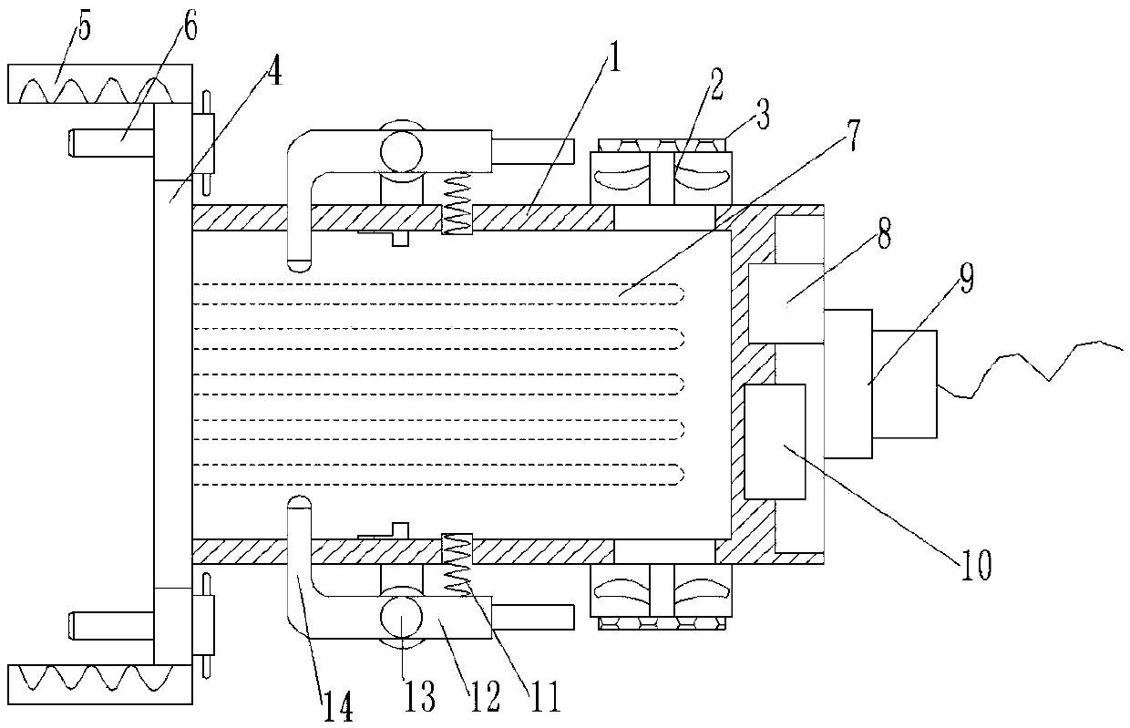
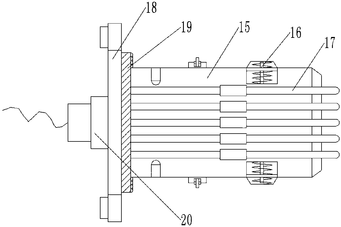
[0018] refer to Figure 1-2 , a connection structure of a network cable joint, comprising a female joint 1, a heat dissipation fan 2 is welded on one side of the outer wall of the female joint 1, and the outer wall of the contact position of the female joint 1 and the heat dissipation fan 2 is provided with equidistantly distributed heat dissipation holes , the air inlet port of the cooling fan 2 is provided with a dust-proof net 3, a first connecting plate 4 is welded on the outer wall of one end of the female joint 1, and threaded holes distributed equidistantly are opened on one side of the outer wall of the first connecting plate 4, And the inner wall of the thre...


PUM


Abstract

The invention discloses a connection structure of network cable joints, comprising a female joint. A radiating fan is welded to the outer wall of one side of the female joint. Equally spaced radiatingholes are formed in the outer wall of the female joint at the position of contact with the radiating fan. A dust-proof net is arranged at the air inlet port of the radiating fan. A first connecting plate is welded onto the outer wall of one end of the female joint. Equally spaced threaded holes are formed in the outer wall of one side of the first connecting plate. A connecting bolt is connectedin a threaded manner to the inner wall of each threaded hole. Equally spaced network cable installation slots are formed in the outer wall of one side of the female joint. A bus binding post is weldedat the middle position of outer wall of one side of the female joint. The occurrence of wire breakage in the use process is avoided, the breakage of network cables due to bending is avoided, and thephenomenon of bad contact between joints is avoided. The connection structure has the advantages of reasonable design, convenient disassembly, low manufacturing cost, high flexibility, reliable contact and durability.

Description

technical field [0001] The invention relates to the technical field of network cable connectors, in particular to a connection structure of network cable connectors. Background technique [0002] To connect to a LAN, a network cable is essential. The common network cables in the local area network mainly include twisted pair, coaxial cable and optical cable. A twisted pair is a data transmission line composed of many pairs of wires. It is characterized by low price, so it is widely used, such as our common telephone lines. It is used to connect with the RJ45 crystal head. It has two kinds of STP and UTP. We commonly use UTP. The existing network cable connectors are dazzling. Difficult to install, thus bringing certain inconvenience to the user, so a connection structure of network cable connector is set up to solve the inconvenience of people in use, such as the design with the publication number CN104600509A, which does not have rotation and is easy to connect functio...

Claims


Application Information

Patent Timeline
Patent Type & Authority Applications(China)
IPC IPC(8): H01R13/639H01R13/52H01R13/502H01R24/00H05K7/20
Inventor 胡学朋
Owner 胡学朋
Why Eureka
Try Eureka