Double-T staggered constrained damping rail

A constrained damping and staggered technology, applied in the field of damping rails, can solve the problems of reducing the comfort of passengers in the car, and achieve the effects of improving vibration and noise reduction, increasing the shear area, and strengthening the shear effect

Active Publication Date: 2019-01-04
TONGJI UNIV
View PDF6 Cites 1 Cited by
  • Summary
  • Abstract
  • Description
  • Claims
  • Application Information

AI Technical Summary

Problems solved by technology

The severe wheel-rail vibration will also reduce the ride comfort of the passengers in the car.

Method used


Image

  • Double-T staggered constrained damping rail

Examples


Embodiment 1

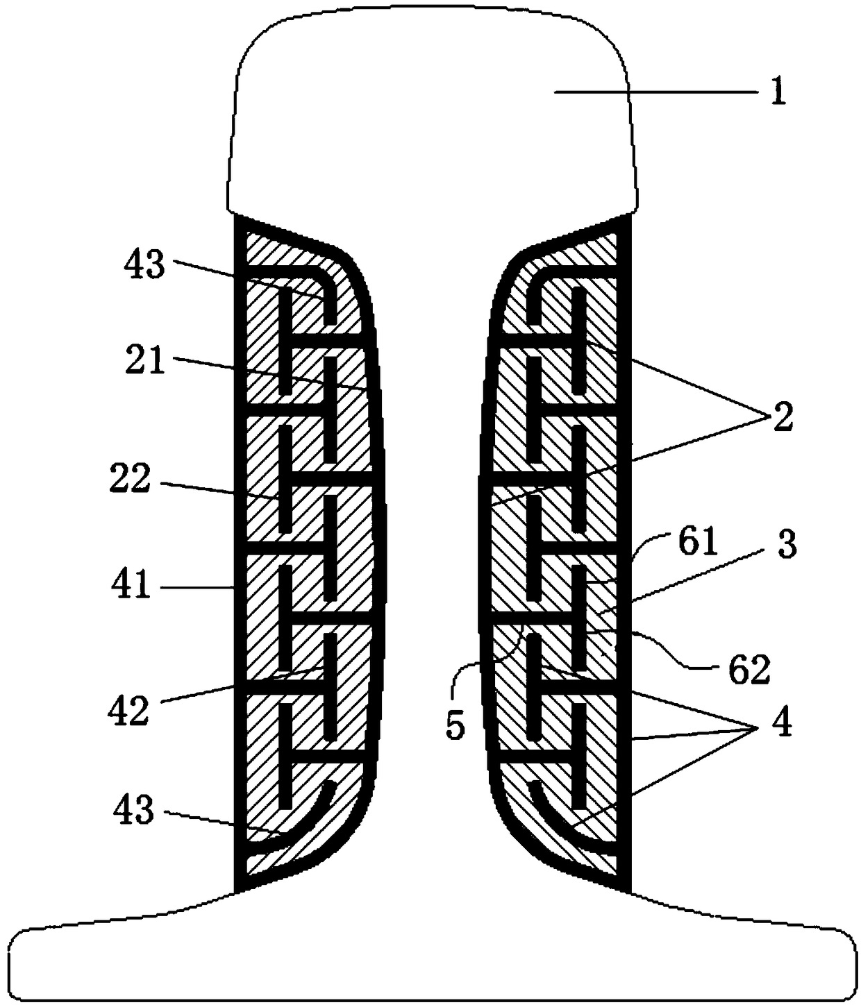
[0024] A kind of double T staggered restrained damping steel rail figure 1 (Shown), including the rail body 1, the T-shaped expansion layer 2, the T-shaped constraining layer 4, and the damping filling layer 3.

[0025] The T-shaped expansion layer 2 is composed of an expansion layer base layer 21 that fits the rail waist and the non-working surface of the rail top of the rail body 1, and a plurality of T-shaped expansion grooves 22 extending outward from the expansion layer base layer 21;

[0026] The T-shaped constrained layer 4 includes a constrained layer outer layer 41 arranged on the periphery of the T-shaped expansion layer 2 and a plurality of T-shaped structural members 42 extending from the constrained layer outer layer 41 to the rail waist, a T-shaped expansion slot 22 and a T-shaped structure The pieces 42 are arranged in a staggered arrangement;

[0027] The damping filling layer 3 is filled in the gap between the T-shaped expansion layer 2 and the T-shaped constraining...


PUM


Abstract

The invention relates to a double-T staggered constrained damping rail, comprising a rail body, a T-shaped expansion layer, a T-shaped restraint layer and a damping filling layer. The T-shaped expansion layer is composed of an expansion layer base layer which is in contact with a non-working surface at a rail waist and a rail top of the rail body, and a plurality of T-shaped expansion grooves which extend from the expansion layer base layer to an outward direction. The T-shaped restraint layer comprises an outer layer of the restraint layer arranged at the periphery of the T-shaped expansion layer and a plurality of T-shaped structural members extending from the outer layer of the restraint layer to the rail waist, wherein the T-shaped expansion grooves and the T-shaped structural membersare mutually engaged and staggered; the damping fill layer is filled between the voids of the T-shaped expansion layer and the T-shaped constraint layer. Compared with the prior art, the invention fully increases the shear area of the damping layer parallel to the longitudinal tangent plane of the rail by constructing the T-type interleaved damping shear structure, enhances the shear effect of thedamping layer by utilizing the integral vertical deformation of the rail, and further improves the vibration and noise reduction effect.

Description

Technical field [0001] The invention relates to a damping steel rail, in particular to a damping steel rail with a T-shaped expansion groove layer and a constraining layer that can make full use of the vertical deformation of the rail and effectively reduce the rail vibration and noise. Background technique [0002] In recent years, with the development of the urban economy and the increase in population, in order to relieve the pressure of urban passenger transportation, the construction of urban rail transit is also in full swing. However, due to the shortage of urban land resources, as the density of rail transit network increases, many rail transit lines will inevitably pass through people's living and office areas. Neighboring building vibration and radiated noise caused by wheel-rail vibration will cause greater trouble to the lives and work of residents along the line, and even affect their physical and mental health in severe cases. The severe wheel-rail vibration will a...

Claims


Application Information

Patent Timeline
IPC IPC(8): E01B5/08E01B19/00
CPCE01B5/08E01B19/003
Inventor 崔日新周劲松宫岛孙文静孙煜
Owner TONGJI UNIV
Why Eureka
Try Eureka