
Road engineering soil milling machine

A kind of earth plowing machine and engineering technology, which is applied in the direction of roads, roads, road repair, etc., can solve the problems of inconvenient adjustment of nozzle angle, limited spraying range, etc., and achieves the effect of simple structure, improved spraying range, and convenient use.

Inactive Publication Date: 2019-01-04
朱世飞
View PDF1 Cites 0 Cited by
  • Summary
  • Abstract
  • Description
  • Claims
  • Application Information

AI Technical Summary

Problems solved by technology

[0003] The patent proposes that the angle of the nozzle in a soil rotary machine for highway engineering is not easy to adjust and the spraying range is limited.

Method used


Image

  • Road engineering soil milling machine
  • Road engineering soil milling machine
  • Road engineering soil milling machine

Examples


Embodiment Construction

[0019] The following will clearly and completely describe the technical solutions in the embodiments of the present invention with reference to the accompanying drawings in the embodiments of the present invention. Obviously, the described embodiments are only some, not all, embodiments of the present invention.

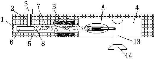
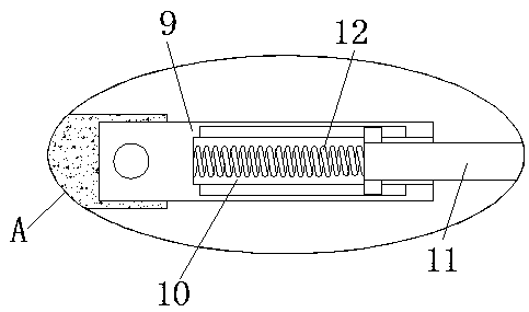
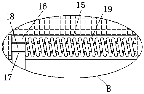
[0020] refer to Figure 1-3 , a soil turning machine for highway engineering, comprising a mounting block 1, the top of the mounting block 1 is provided with a turning hole 2, the top of the mounting block 1 is fixedly installed with a motor 3, and the bottom of the mounting block 1 is provided with a placement groove 4, and the placement groove 4 There is a first chute 5 on the inner wall near the rotation hole 2, the first chute 5 is located below the motor 3, and the first chute 5 communicates with the rotation hole 2, and the output shaft of the motor 3 extends through the rotation hole 2 Into the first chute 5 and welded with an eccentric wheel 6, a slide bar 7 ...


PUM


Abstract

The invention discloses a road engineering soil milling machine which comprises a mounting block, wherein a rotating hole is formed in the top of the mounting block; a motor is fixedly mounted at thetop of the mounting block; a holding groove is formed in the bottom of the mounting block; a first chute is formed in the inner wall of one side close to the rotating hole, of the holding groove; thefirst chute is positioned below the motor; the first chute is communicated with the rotating hole; the output shaft of the motor penetrates through the rotating hole and extends into the first chute and is welded with an eccentric gear; a sliding rod is mounted inside the first chute in a sliding manner; the sliding rod is matched with the eccentric gear; one side of the sliding rod extends into the holding groove; a first connecting rod is rotationally mounted on one side of the sliding rod; a second chute is formed in one side far away from the first chute, of the first connecting rod. By adopting the road engineering soil milling machine, a nozzle can be swung back and forth, then the spraying range of the nozzle can be increased, the problem of dead angles of spraying is avoided, and the road engineering soil milling machine is simple in structure and convenient to use.

Description

technical field [0001] The invention relates to the technical field of earth turning machines, in particular to an earth turning machine for highway engineering. Background technique [0002] With the rapid development of social economy, modern people's demand for traffic is getting higher and higher. The country strongly supports the construction of road traffic, and road traffic has developed rapidly. The mileage of roads is not increasing. , Highway construction requires the use of soil rotary machines. After searching, the patent document with the application number 201721438793.0 discloses a soil turning machine for road engineering, which includes a body, a handle is fixedly connected to one side of the top of the body, and a box is fixedly connected to the top of the inner cavity of the body, and the inside of the box is fixed. A motor is installed, the output shaft of the motor is connected to the rotating shaft of the main shaft through a transmission belt, the sur...

Claims


Application Information

Patent Timeline
IPC IPC(8): E01C21/00
CPCE01C21/00
Inventor 朱世飞
Owner 朱世飞
Learn More