
Adjustable power equipment guardrail

An electric device and adjustable technology, which is applied in the direction of fences, building types, buildings, etc., can solve the problems of poor protection effect of the fence, lack of bird repelling function, inconvenient connection of multiple fences, etc., and achieve the purpose of improving the fixing effect Effect

Inactive Publication Date: 2019-01-04
宋盈盈
View PDF8 Cites 4 Cited by
  • Summary
  • Abstract
  • Description
  • Claims
  • Application Information

AI Technical Summary

Problems solved by technology

[0006] In order to solve the above technical problems, the present invention provides an adjustable power equipment guardrail, to solve the problem that the existing power equipment guardrail has poor protection effect on the outside of the guardrail, and the distance between the guardrails cannot be adjusted according to the needs of use. The fixing effect of the guardrail is poor, and it is inconvenient to connect multiple guardrails together when the guardrail needs to be used in a large area. It does not have the function of repelling birds and cannot adjust the width of the guardrail according to the needs of use.

Method used


Image

  • Adjustable power equipment guardrail
  • Adjustable power equipment guardrail
  • Adjustable power equipment guardrail

Examples


Embodiment

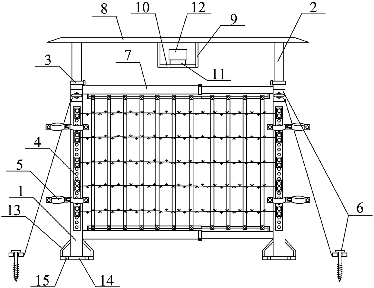
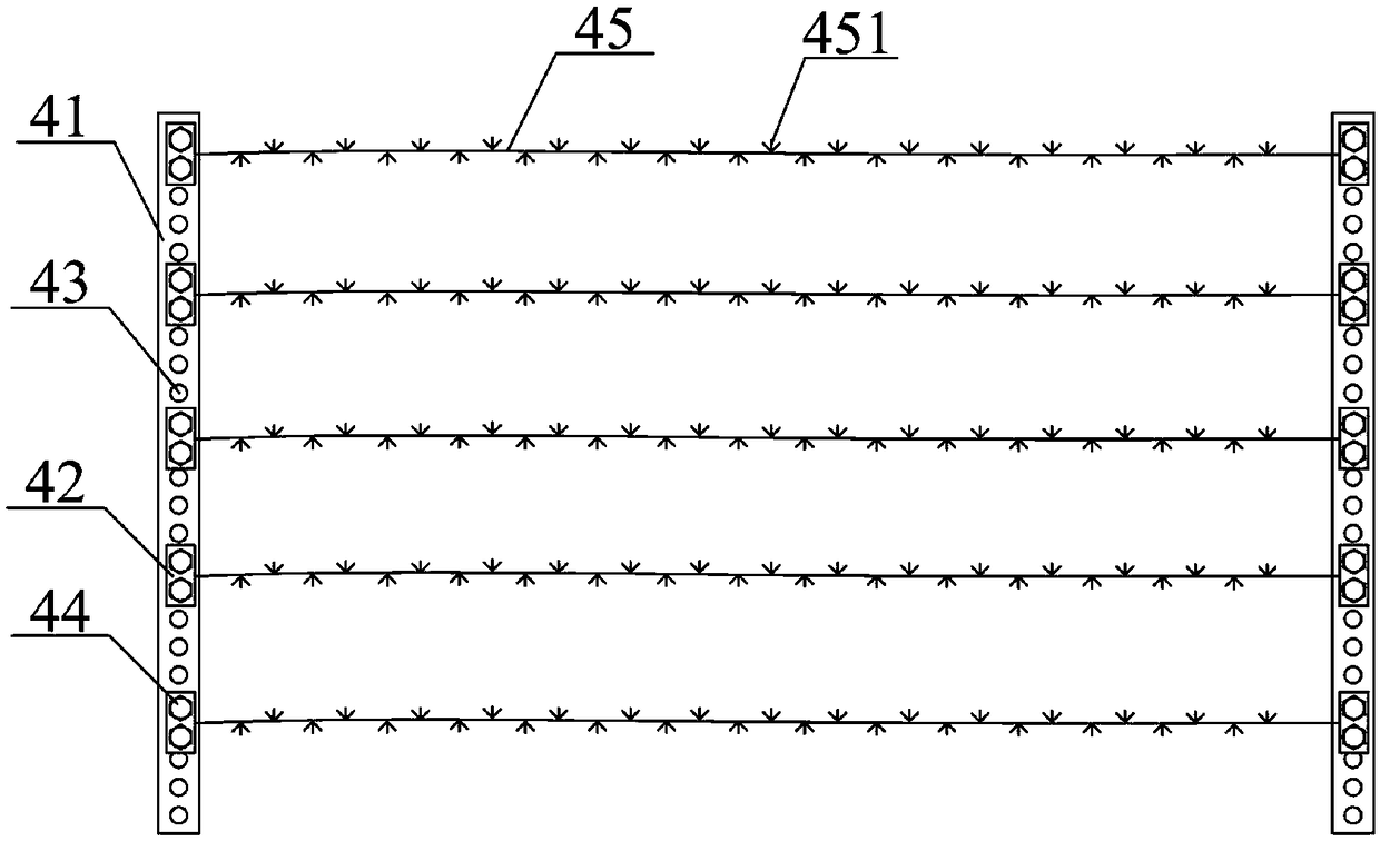
[0039] as attached figure 1 And attached figure 2 shown

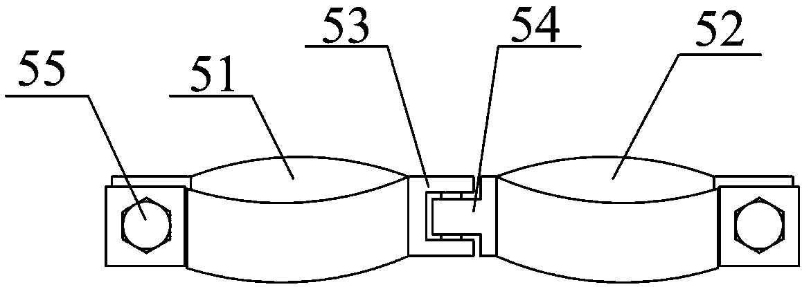
[0040] The present invention provides an adjustable electric equipment guardrail, comprising a supporting sleeve 1, a longitudinal support rod 2, a quick-release buckle 3, an adjustable guardrail structure 4, a guardrail connecting frame structure 5, a reinforced foundation structure 6, and an adjustable guardrail frame Structure 7, PVC transparent rain cover 8, longitudinal connecting rod 9, horizontal mounting plate 10, connecting seat 11, bird repellent 12, reinforcing frame 13, fixed bottom plate 14 and fixed jack 15, the longitudinal pole 2 plug Connected to the inner upper part of the support sleeve 1; the quick release buckle 3 is sleeved on the outside of the support sleeve 1 and the longitudinal strut 2; the adjustable guardrail structure 4 is installed on the front of the support sleeve 1 The guardrail connecting frame structure 5 is installed on the left and right sides of the support sleeve 1; the reinforce...


PUM


Abstract

The invention provides an adjustable power equipment guardrail. The adjustable power equipment guardrail comprises supporting sleeves, longitudinal supporting rods, quick release buckles, adjustable protective fence structures, guardrail connecting frame structures, reinforcing foot structures, an adjustable guardrail frame structure, a PVC transparent rain shade, longitudinal connecting rods, a transverse mounting plate, a connecting seat, a bird repeller, reinforcing frames, fixing bottom plates and fixing inserting holes; the longitudinal supporting rods are inserted in the upper parts of the internal sides of the supporting sleeves; and the quick release buckles are connected to the external sides of the supporting sleeves and the external sides of the longitudinal supporting rods in asleeving manner. According to the adjustable power equipment guardrail, metal barbed nails are welded on the external sides of steel wire protective ropes to be beneficial for preventing working personnel from climbing the guardrail so as to prevent the guardrail from being damaged; longitudinal guardrails are correspondingly connected to the external sides of L-shaped sleeves and the external sides of L-shaped inserting rods through fixing sleeves to be beneficial for adjusting the distances between the longitudinal guardrails according to use needs; and fixing holes and T-shaped bolts are also arranged on mounting bottom plates to be beneficial for improving the fixing effect of the guardrail during using.

Description

technical field [0001] The invention belongs to the technical field of guardrails, in particular to an adjustable electric equipment guardrail. Background technique [0002] When maintaining power equipment, maintenance personnel will set up fences around the power facilities to prevent non-professionals from accidentally touching the power equipment and avoid electric shock accidents. The existing fence cannot effectively prevent people from climbing due to its height. [0003] The Chinese patent application number is 201611016590.2. The name of the invention is a guardrail for electric equipment, including a front guardrail, a rear guardrail, a base and two support rods. A movable guardrail is arranged between the front guardrail and the rear guardrail. The front guardrail, the rear guardrail and the The mobile guardrail includes an upper cross bar and a lower cross bar, and a plurality of vertical bars are fixed between the upper cross bar and the lower cross bar. The upp...

Claims


Application Information

Patent Timeline
Patent Type & Authority Applications(China)
IPC IPC(8): E04H17/00E04H17/14
CPCE04H17/00E04H17/003E04H17/14E04H17/1413E04H17/1447
Inventor 宋盈盈
Owner 宋盈盈
Learn More