
Semiautomatic electronic lock with dissociation protection

An electronic lock and semi-automatic technology, applied in the field of door locks, can solve the problems of easy damage of the lock body, low firmness and installation strength, poor anti-theft performance, etc., and achieve the effect of high transmission efficiency, simple structure and stable operation

Active Publication Date: 2019-01-04
浙江威欧希科技股份有限公司
View PDF8 Cites 6 Cited by
  • Summary
  • Abstract
  • Description
  • Claims
  • Application Information

AI Technical Summary

Problems solved by technology

[0002] Most of the door locks installed on the market today are electronic door locks, because electronic locks have the advantages of simple operation, high security, and not easy to be damaged. Existing electronic locks are generally provided with authentication components such as password components or fingerprint components. When entering the door from the outside, it is necessary to verify the fingerprint or password. After the verification is successful, the main bolt pick, limit stopper, oblique bolt pick, oblique bolt connecting piece and main deadbolt connecting piece in the lock body will open the door. The parts start to work so that the main tongue and the oblique tongue move inward. After the movement is completed, the handle of the door can be opened to complete the door. However, the existing electronic lock body will be provided with a function to limit the rotation of the door handle before the fingerprint or password is verified. The push-pull handle limit mechanism is connected with the door opening assembly in the lock body. Because the parts of this handle limit mechanism are relatively small in size, the firmness and installation strength are relatively low. Criminals only need to forcefully turn or push the door handle. Destroying the door opening components in the lock body, the anti-theft performance is poor, and the lock body is easily damaged after long-term use

Method used


Image

  • Semiautomatic electronic lock with dissociation protection
  • Semiautomatic electronic lock with dissociation protection
  • Semiautomatic electronic lock with dissociation protection

Examples


Embodiment Construction

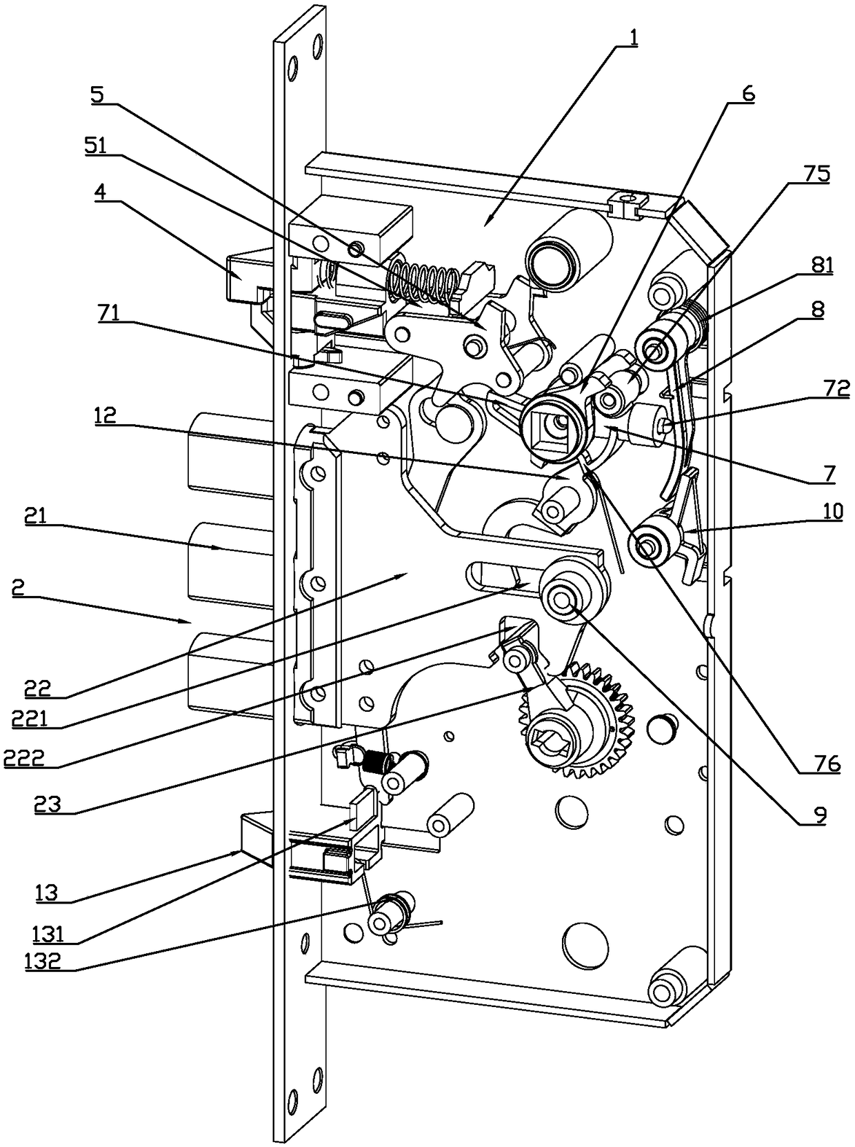
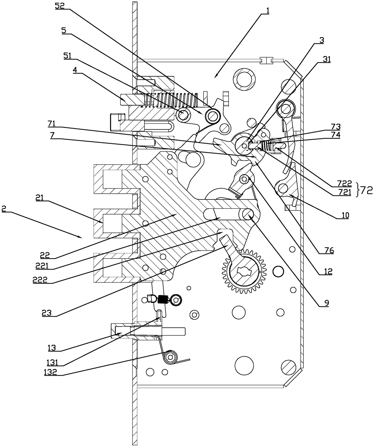
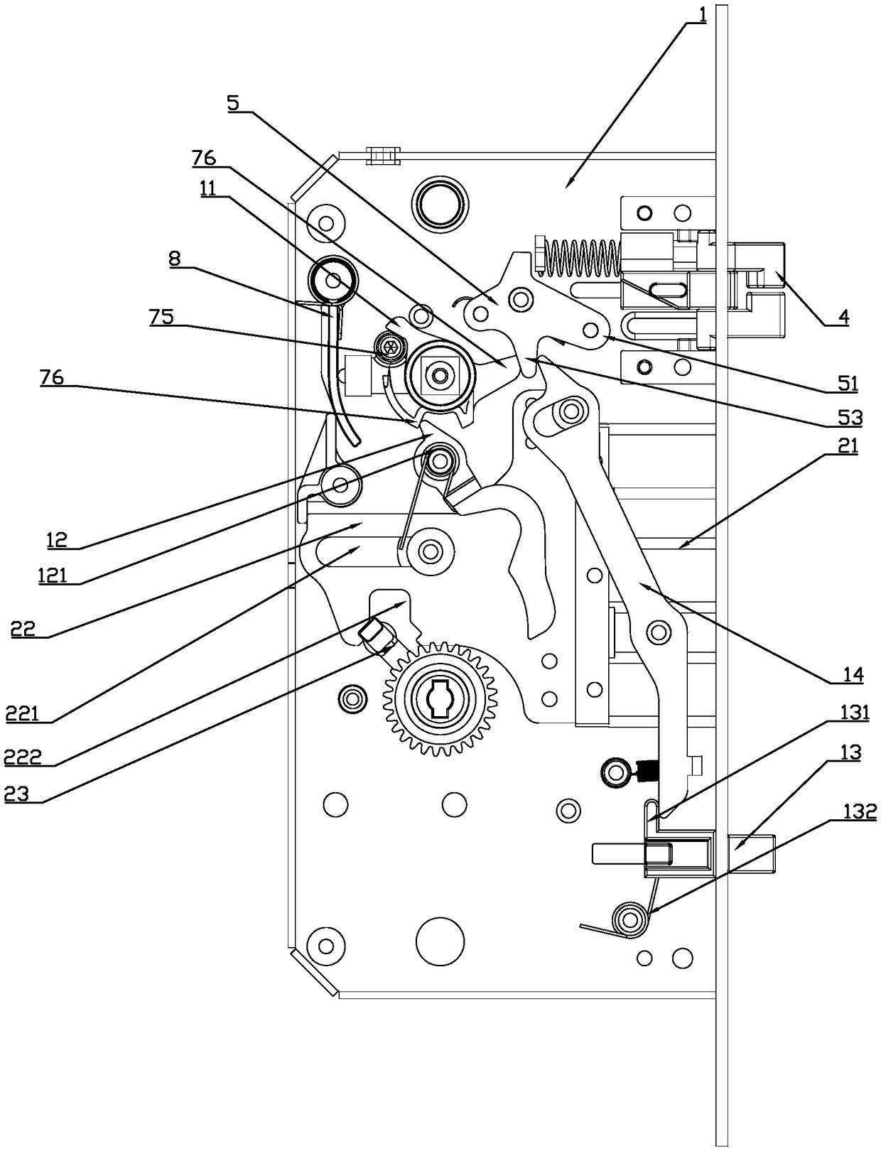
[0024] Depend on Figure 1 to Figure 6It can be seen that the present invention discloses a semi-automatic electronic lock body with free protection, including a lock case 1, on which a main bolt assembly 2, a clutch 3 and a retractable bolt 4 are arranged, and the lock The shell 1 is also hinged with a latch bolt stopper 5, which includes a stopper 51 for restricting the extension and contraction of the latch bolt 4, and the clutch 3 is sleeved with an outer latch that is linked with the clutch 3. Clutch block 6, the main bolt assembly 2 includes a motor, a verification unit and a main bolt 21 for opening the door, the main bolt 21 is movably arranged on the side wall of the lock housing 1, and the motor is electrically connected to the verification unit , the output end of the motor is connected to the main dead bolt 21 in transmission, after the verification unit is energized, the motor starts to work and drives the main dead bolt 21 to shrink into the housing 1, thereby co...


PUM


Abstract

The invention discloses a semiautomatic electronic lock with dissociation protection. The semiautomatic electronic lock comprises a lock shell. A main spring bolt assembly, a clutch and a latch bolt are arranged on the lock shell. A latch bolt limiting part is further hinged to the lock shell. The latch bolt limiting part comprises a limiting portion, and the clutch is sleeved with an outer clutchblock. The main spring bolt assembly comprises a motor, a verifying unit and a main spring bolt, the output end of the motor is in transmission connection with the main spring bolt, and the clutch issleeved with a square steel rotating shaft. The square steel rotating shaft is provided with a first rotating shaft stirring foot, and the square steel rotating shaft is further movably provided witha clutch pin. An insertion groove is formed in the clutch, and the clutch pin is inserted in the insertion groove to achieve linkage of the square steel rotating shaft and the clutch. A clutch pin reset spring is further arranged in the square steel rotating shaft. A clutch push part is hinged to the lock shell, and the clutch push part is in transmission connection with the output end of the motor. By means of the semiautomatic electronic lock, dissociation between a door handle and the structure in the lock body is achieved, and the antitheft performance is good.

Description

technical field [0001] The invention relates to the field of door locks, in particular to a semi-automatic electronic lock body with free protection. Background technique [0002] Most of the door locks installed on the market are now electronic door locks, because electronic locks have the advantages of simple operation, high security, and not easy to be damaged. Existing electronic locks are generally provided with authentication components such as password components or fingerprint components. When entering the door from the outside, it is necessary to verify the fingerprint or password. After the verification is successful, the main bolt pick, limit stopper, oblique bolt pick, oblique bolt connecting piece and main deadbolt connecting piece in the lock body will open the door. The parts start to work so that the main tongue and the oblique tongue move inwardly. After the movement is completed, the door handle can be operated to complete the door opening. However, the exi...

Claims


Application Information

Patent Timeline
IPC IPC(8): E05B47/00E05B15/00E05B15/10E05B63/14
CPCE05B15/00E05B15/10E05B47/0012E05B47/026E05B47/06E05B63/146E05B2047/0026Y02T10/70
Inventor 周烨林飞和
Owner 浙江威欧希科技股份有限公司
Learn More