LED high-pole lamp

A technology of LED high pole lights and bottom brackets, applied in outdoor lighting, lighting and heating equipment, mechanical equipment, etc., can solve the problems of inconvenient repair, maintenance and replacement

Active Publication Date: 2019-01-04
YANGZHOU DIANDI LIGHTING CO LTD
View PDF10 Cites 2 Cited by
  • Summary
  • Abstract
  • Description
  • Claims
  • Application Information

AI Technical Summary

Problems solved by technology

[0002] For example, the publication number CN207687949U is a kind of LED high pole lamp, including a column, one end of the column is provided with a fixing device, the other end of the column is connected with a support frame, the support frame is provided with a lampshade, and the support frame is connected There is a lightning rod, and first mounting grooves are symmetrically arranged on the column, and a first mounting plate is slidably connected to each of the first mounting grooves, and a ladder is connected to the first mounting plate, and a ladder is connected to the first mounting groove. It is also rotatably connected with a second rotating shaft, and a revolving door is interspersed on the second revolving shaft, and one end of the revolving door is provided with a gear, and the gear is inserted on the second rotating shaft; the disadvantage of this utility model is that it is inconvenient to repair and repair LED etc. for maintenance and replacement

Method used


Image

  • LED high-pole lamp
  • LED high-pole lamp
  • LED high-pole lamp

Examples


specific Embodiment approach 1

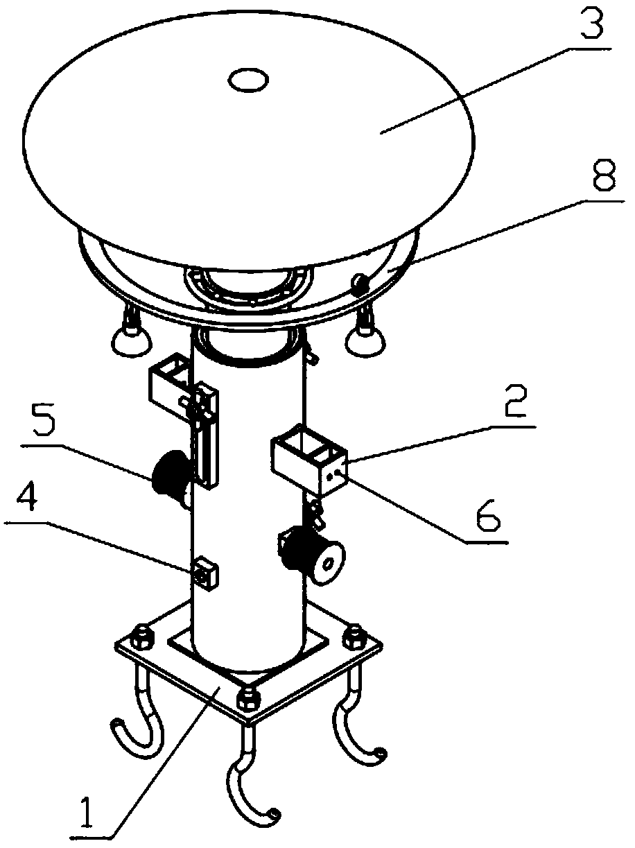
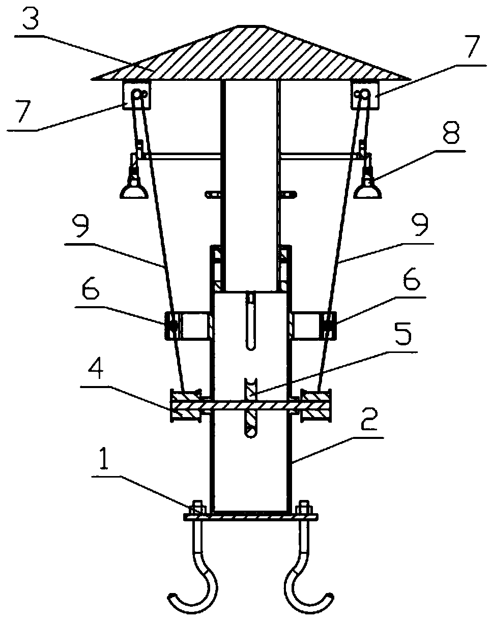
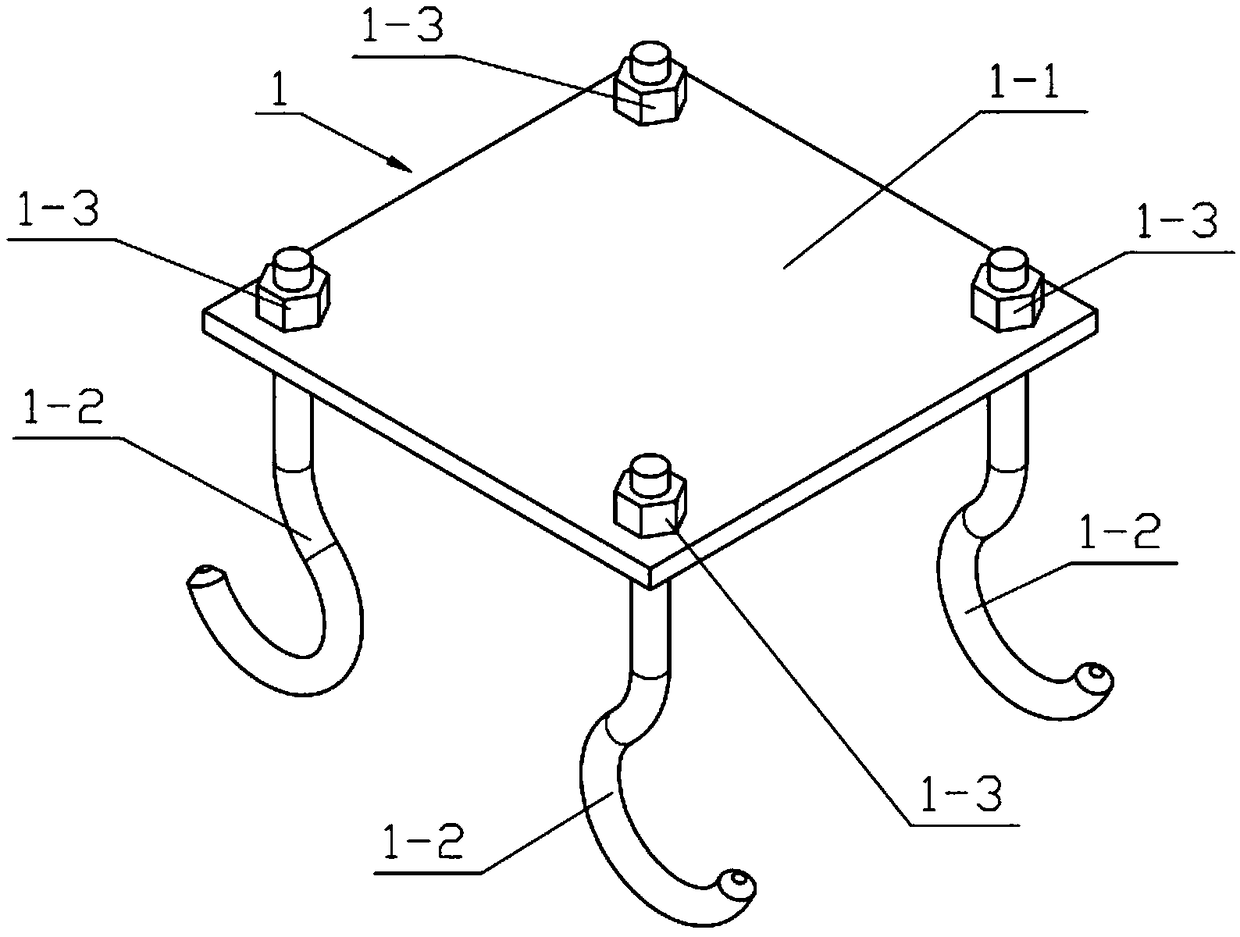
[0038] Combine below Figure 1-16 Explaining this embodiment, an LED high pole lamp includes a bottom bracket 1, an integral bracket 2, a lifting bracket 3, a power mechanism 4, a reel mechanism 5, a gear wheel I 6, a gear wheel mechanism 7, a lamp holder 8 and a wire rope 9. The reel mechanism 5 can be driven to rotate by manually turning the power mechanism 4, and the two reels 5-3 rotate in the same direction to drive the two wire ropes 9 to be wound on the two reels 5-3. The gear wheel I6 limits the wire ropes 9 on both sides to prevent the wire rope 9 from detaching. The two gear wheel mechanisms 7 on both sides limit the wire ropes 9 on both sides to prevent the wire ropes 9 on both sides from leaving the gear wheel body Ⅱ 7- 4. Ensure the movement trajectory of the wire rope 9. The wire rope 9 drives the lamp holder 8 to move up and down so that the lamp holder 8 can fall to the lower end of the device. The staff can maintain and repair the lamp holder 8 without high-alt...

specific Embodiment approach 3

[0048] Combine below Figure 1-16 To explain this embodiment, this embodiment further explains the second embodiment. The integral bracket 2 also includes a sliding mounting block 2-5 and a vertical sliding groove 2-6. The front and rear ends of the bracket cylinder 2-2 are fixedly connected. There are sliding mounting blocks 2-5, and vertical sliding grooves 2-6 are provided on the two sliding mounting blocks 2-5.

specific Embodiment approach 4

[0049] Combine below Figure 1-16 To explain this embodiment, this embodiment further explains the third embodiment. The lifting bracket 3 further includes a lifting handle 3-3, a lifting rotating plate 3-4, a lifting sliding column 3-5, and a lifting locking handle 3-6 , The lifting rotating plate 3-4 is rotatably connected to the lower end of the lifting cylinder 3-1, both sides of the lifting rotating plate 3-4 are fixedly connected with lifting sliding columns 3-5, and the two lifting sliding columns 3-5 are threaded The lifting locking handles 3-6 are connected, the two lifting sliding posts 3-5 are slidably connected in the two vertical sliding grooves 2-6, and the two lifting locking handles 3-6 are connected to the two sliding mounting blocks 2 respectively. -5 contacts.


PUM


Abstract

The invention relates to a high-pole lamp, in particular to an LED high-pole lamp. The LED high-pole lamp comprises a bottom support, an overall support, a lifting support, a power mechanism, a reel mechanism, gear wheels II, gear wheel mechanisms, lamp brackets and steel wire ropes. The power mechanism can be rotated manually to drive the reel mechanism to rotate, and the rotating directions of two reels are the same, so that the two steel wire ropes are driven to wind around the two reels; the steel wire ropes on the two sides are limited by the two gear wheels I on the two sides and prevented from being separated, the steel wire ropes on the two sides are limited by the two gear wheel mechanisms on the two sides and prevented from being separated from gear wheels II, the motion track ofthe steel wire ropes is guaranteed, the lamp brackets are driven by the steel wire ropes to move up and down and can drop to the lower end of the lamp, and the lamp brackets can be maintained and repaired by a worker without working aloft.

Description

Technical field [0001] The invention relates to a high-pole lamp, and more specifically to an LED high-pole lamp. Background technique [0002] For example, the publication number CN207687949U is an LED high pole lamp, which includes a column, one end of the column is provided with a fixing device, the other end of the column is connected with a support frame, the support frame is provided with a lamp shade, and the support frame is connected There is a lightning rod, first mounting grooves are symmetrically provided on the column, a first mounting plate is slidably connected to each of the first mounting grooves, a climbing ladder is connected to the first mounting plate, and the first mounting groove is A second rotating shaft is also rotatably connected, and a rotating door is inserted on the second rotating shaft. One end of the rotating door is provided with a gear, and the gear is inserted on the second rotating shaft. The disadvantage of this utility model is that it is no...

Claims


Application Information

Patent Timeline
Patent Type & Authority Applications(China)
IPC IPC(8): F21S8/08F21V21/36F21W131/103F21Y115/10
CPCF21S8/085F21V21/36F21W2131/103F21Y2115/10
Inventor 李纪旋
Owner YANGZHOU DIANDI LIGHTING CO LTD
Why Eureka
Try Eureka