Light guide plate and preparation method thereof

A technology of light guide plate and fluorescent ink, applied in the field of light guide plate, can solve the problems of low adhesion, poor dot printing effect of light guide plate, affecting the light output effect of backlight module, etc., and achieve good light effect

Pending Publication Date: 2019-01-04
惠州安嵘光电产品有限公司
View PDF0 Cites 4 Cited by
  • Summary
  • Abstract
  • Description
  • Claims
  • Application Information

AI Technical Summary

Problems solved by technology

In the prior art, the dots of the light guide plate are produced by using screen printing technology to directly print ink on the surface of the light guide plate, but the ink directly printed on t

Method used


Image

  • Light guide plate and preparation method thereof
  • Light guide plate and preparation method thereof
  • Light guide plate and preparation method thereof

Examples


Embodiment 1

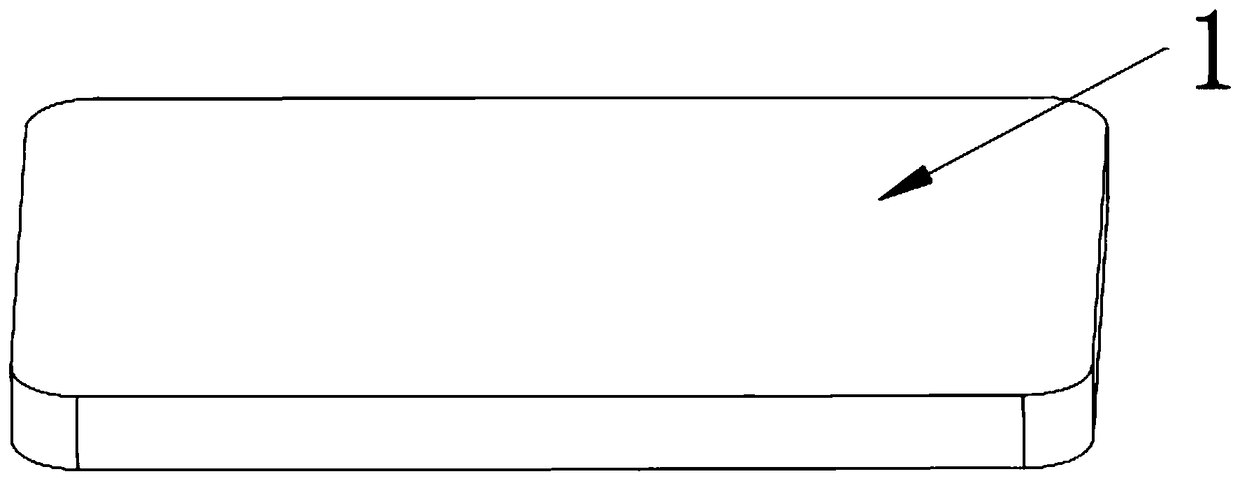
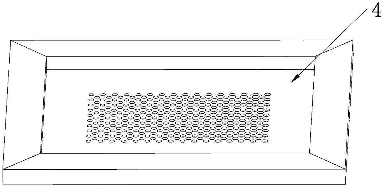
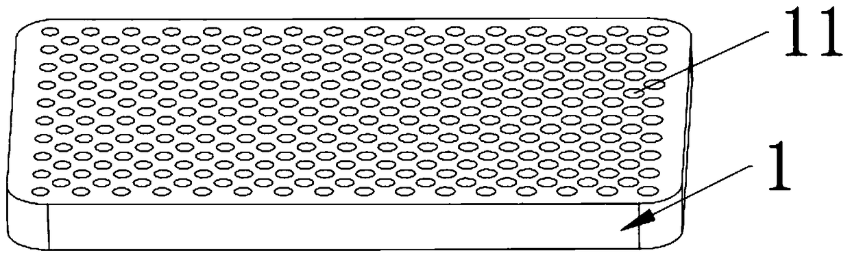
[0039] refer to Figure 1 to Figure 5 , figure 1 It is a schematic diagram of the structure of the light guide plate body when it is not etched, figure 2 is a schematic diagram of the screen structure, image 3 It is a schematic diagram of the structure of the light guide plate body after etching, Figure 4 It is a cross-sectional view of the light guide plate body after etching on one side, Figure 5 It is a cross-sectional view of the main body of the light guide plate after printing on one side. In this embodiment, the light guide plate includes a light guide plate body 1 and a plurality of first printing dots 2 printed on the light guide plate body 1 .

[0040] The light guide plate body 1 is a transparent plate made of PMMA material, that is, an acrylic plate; the light guide plate body 1 in this embodiment is a rectangular plate with a thickness of 6mm, and one side of the light guide plate body 1 is provided with a plurality of dislocation-arranged first One netwo...

Embodiment 2

[0048] refer to Figure 8 , Figure 8 It is one of the flowcharts of the preparation method of the light guide plate, and the preparation method of the light guide plate in this embodiment includes the following steps:

[0049] S1, making a screen 4, on which optical dots are formed; the optical dots are designed first, and then a stencil is made according to the design of the optical dots. In this embodiment, the optical dot design can be designed by GTOOLS LGP software. Specifically, the optical dot design is carried out according to the dislocation arrangement of the first dot slots 11 in Embodiment 1, and then the corresponding steel mesh is made through the screen making process Version.

[0050] S2, the screen plate 4 is placed on one side of the light guide plate body 1, and screen printing is performed with an organic solvent, so that one side of the light guide plate body 1 is etched to form a plurality of first dot grooves 11 recessed into the light guide plate bod...


PUM

PropertyMeasurementUnit
Thicknessaaaaaaaaaa

Abstract

The present invention provides a light guide plate. The light guide plate comprises a light guide plate body and a plurality of first printing dots, one surface of the light guide plate is provided with a plurality of first dot grooves in a derangement mode, one gaps is arranged between each two adjacent first dot grooves; the first dot grooves are internally provided with a plurality of printingdots in a printing mode through adoption of the screen printing plate printing technology, and the height of the first printing dots is larger than the depth of the first dot grooves. The present invention further provides a preparation method of a light guide plate. The method comprises the following steps of: preparing a screen printing plate, etching the screen printing plate by employing an organic solvent to form the first dot grooves, performing water washing and printing ink to form first printing dots, and performing printing ink solidification. The organic solvent is employed to perform etching for the light guide plate body to form the first dot grooves in a groove state at the surface of the light guide plate body, the printed first printing dots are stably connected with the internal portion of the groove-shaped first dot grooves, and the prepared light guide plate is applied on a panel lamp so as to have a good light effect.

Description

technical field [0001] The present invention relates to the technical field of light guide plates, in particular to a light guide plate and a preparation method thereof. Background technique [0002] The light guide plate is used to convert the line light source of the backlight into a surface light source with uniform brightness. In order to improve the uniformity of light emission, generally multiple dots are set on the surface of the light guide plate to destroy the total reflection condition of the light beam transmitted inside the light guide plate. Further, the overall optical performance of the backlight module can be improved. In the prior art, the dots of the light guide plate are produced by using screen printing technology to directly print ink on the surface of the light guide plate, and the ink directly printed on the surface of the light guide plate has a low adhesion, so that the printing effect of the dots on the light guide plate is poor, which in turn affec...

Claims


Application Information

Patent Timeline
IPC IPC(8): G02B6/00
CPCG02B6/004G02B6/0043G02B6/0065
Inventor 邝继琛刘锡
Owner 惠州安嵘光电产品有限公司
Why Eureka
Try Eureka