
Compensation display screen, in-screen optical system and electronic device

An optical system and display technology, applied in the field of electronics, can solve the problems of full, high screen ratio, difficult display, etc., to avoid the effect of diffraction and improve the quality and effect.

Active Publication Date: 2019-01-04
SHENZHEN ORBBEC CO LTD
View PDF8 Cites 34 Cited by
  • Summary
  • Abstract
  • Description
  • Claims
  • Application Information

AI Technical Summary

Problems solved by technology

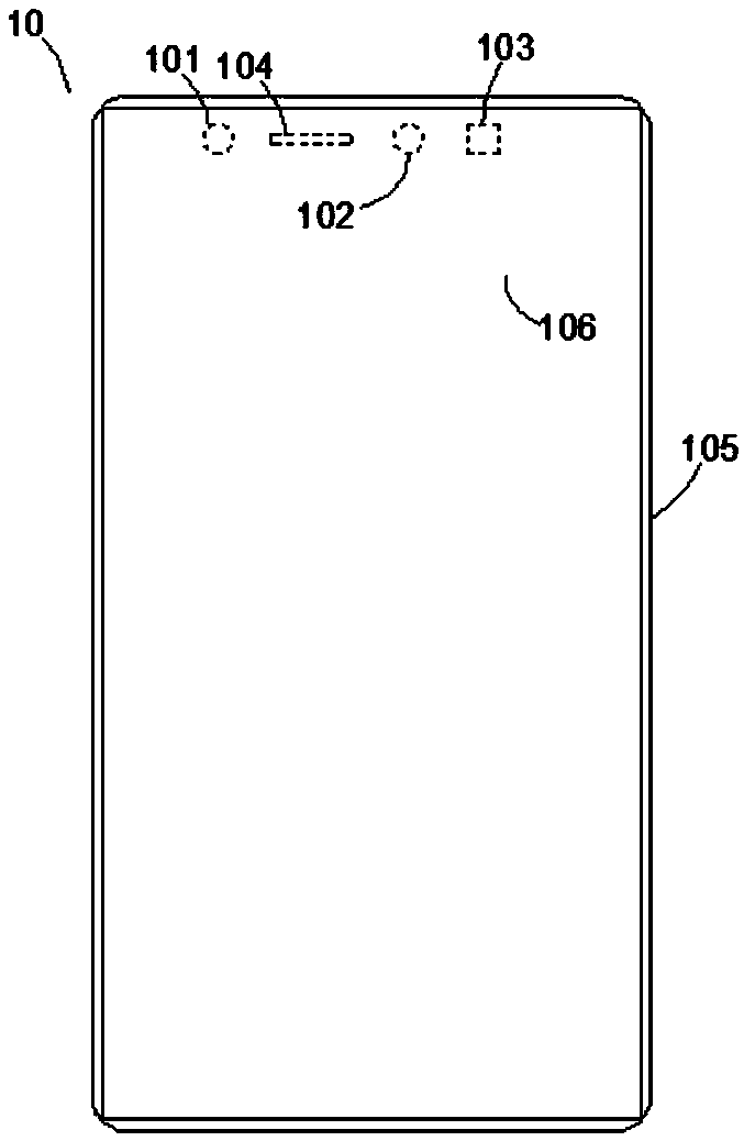
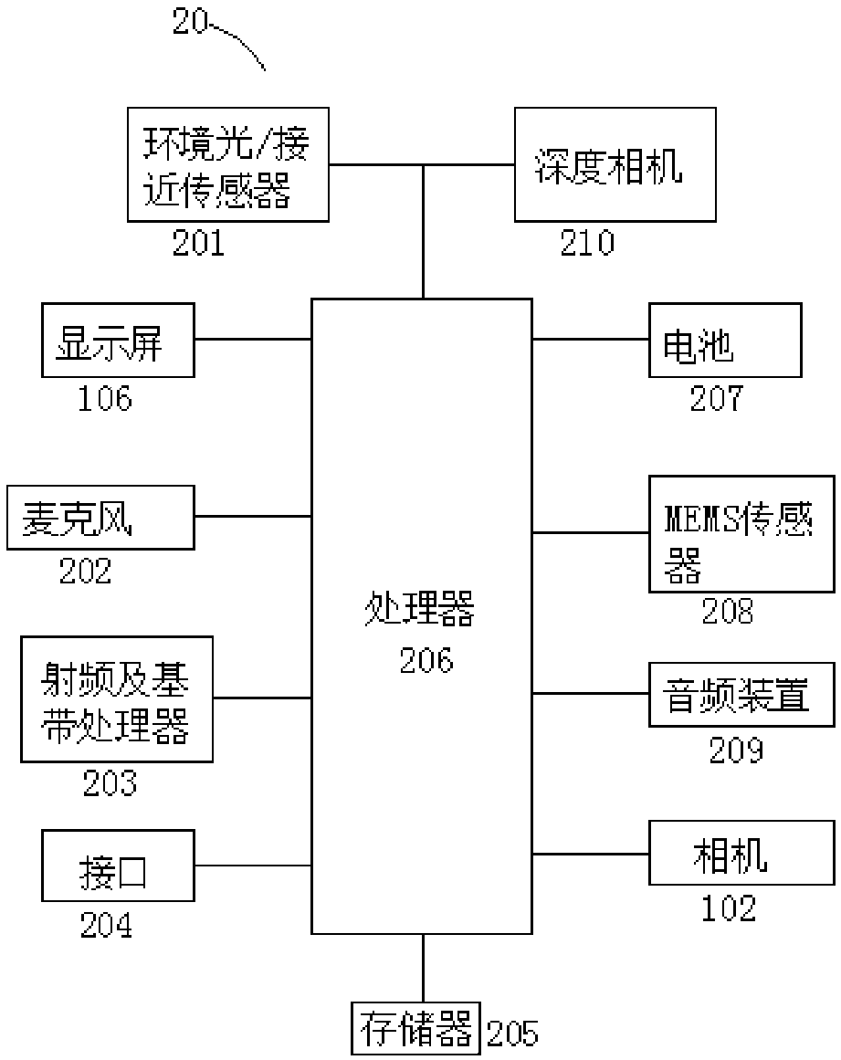
The challenge faced by current full-screen electronic devices is the conflict between the front camera and the display screen. The existence of the front camera makes it difficult for the display screen to fill the entire front of the phone in a true sense in order to achieve a higher screen-to-body ratio.
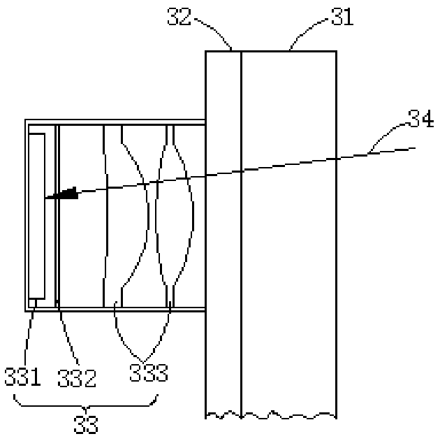
[0004] Setting the optical module on the back of the display screen can realize a full screen, and the display screen is located in the front for displaying the picture. The light received or emitted by the optical module will pass through the display screen, but since the display screen is composed of multiple horizontal and vertical Multiple pixel units form a periodic pixel diffraction structure, so the display screen will have a diffraction effect on the incident light beam, which will eventually lead to a decrease in the projection or imaging quality of the optical module set on the back of the display screen

Method used


Image

  • Compensation display screen, in-screen optical system and electronic device
  • Compensation display screen, in-screen optical system and electronic device
  • Compensation display screen, in-screen optical system and electronic device

Examples


Embodiment Construction

[0030] In order to make the object, technical solution and advantages of the present invention clearer, the present invention will be further described in detail below in conjunction with the accompanying drawings and embodiments. It should be understood that the specific embodiments described here are only used to explain the present invention, not to limit the present invention.

[0031] It should be noted that when a component is referred to as being “fixed on” or “disposed on” another component, it may be directly or indirectly on the other component. When an element is referred to as being "connected to" another element, it can be directly or indirectly connected to the other element. The orientation or positional relationship indicated by the terms "upper", "lower", "left", "right", etc. are based on the orientation or positional relationship shown in the drawings, and are for convenience of description only, rather than indicating or implying the referred device Or ele...


PUM


Abstract

The invention is applicable to the technical field of electronics, and provides a compensation display screen, an in-screen optical system and an electronic device. The compensation display screen comprises a transparent display screen consisting of a plurality of periodically arranged pixel units used for displaying, and a compensation component, wherein the transparent display screen includes aplurality of periodically arranged pixel units used for displaying, and the compensation component is configured to be complementary to the diffraction effect of the transparent display screen, so that the same preset light beam is emitted after the preset light beam enters the compensation display screen. The compensation component which is complementary to the diffraction effect of the transparent display screen is arranged, and the diffraction effect caused by the periodic pixel diffraction structure of the light beam passing through the transparent display screen is counteracted, so that when the preset light beam enters the compensation display screen to be emitted out as the same preset light beam, the diffraction effect of the transparent display screen on incident light beams is avoided, and the quality and effect of imaging or projection are improved.

Description

technical field [0001] The invention belongs to the field of electronic technology, and in particular relates to a compensation display screen, an optical system under the screen and electronic equipment. Background technique [0002] Taking photos and displaying is an essential function of many electronic devices at present. Front cameras and displays are installed on the front of electronic devices to meet various needs, such as Selfie, content display, touch interaction, etc. [0003] As people have higher and higher requirements for the aesthetics of mobile phones, full-screen electronic devices, such as full-screen mobile phones, have gradually become a new direction for mobile phone innovation, because full-screen mobile phones have a very high screen-to-body ratio, are easy to control, and are very aesthetically pleasing visual impact. The challenge faced by current full-screen electronic devices is the conflict between the front camera and the display screen. The ex...

Claims


Application Information

Patent Timeline
IPC IPC(8): G02B27/42
CPCG02B27/42G02B27/4205G02F1/31G02B5/1866
Inventor 朱亮杨鹏许星
Owner SHENZHEN ORBBEC CO LTD
Learn More