System and method for determining the direction and spacing of fiber paths for a composite ply

A composite material layer and composite material technology, applied in the direction of analyzing materials, complex mathematical operations, comprehensive factory control, etc., can solve problems such as non-parallel, not considered, and inability to consider the influence of convergence and manufacturability

Active Publication Date: 2019-01-04
THE BOEING CO
View PDF18 Cites 3 Cited by
  • Summary
  • Abstract
  • Description
  • Claims
  • Application Information

AI Technical Summary

Problems solved by technology

However, for composite plies with curved profiles and / or non-constant fiber angle distributions, fiber paths following the fiber directions specified in the fiber angle distribution may not be parallel to each other
As a result, the courses may converge and / or diverge at certain locations of the composite plies, resulting in overlap and / or gaps between adjacent courses
Overlap and gaps can negatively affect the structural properties (e.g., strength, stiffness), surface quality, and manufacturability of composite laminates
Furthermore, design engineers do not have the ability to consider the effects of convergence and divergence on the manufacturability of composite laminates, which can lead to costly and time-consuming rework of composite laminates during fabrication
Additionally, the inability to account for convergence and divergence during the design phase of composite laminates can mean that more efficient designs are never considered

Method used


Image

  • System and method for determining the direction and spacing of fiber paths for a composite ply
  • System and method for determining the direction and spacing of fiber paths for a composite ply
  • System and method for determining the direction and spacing of fiber paths for a composite ply

Examples


Embodiment 1

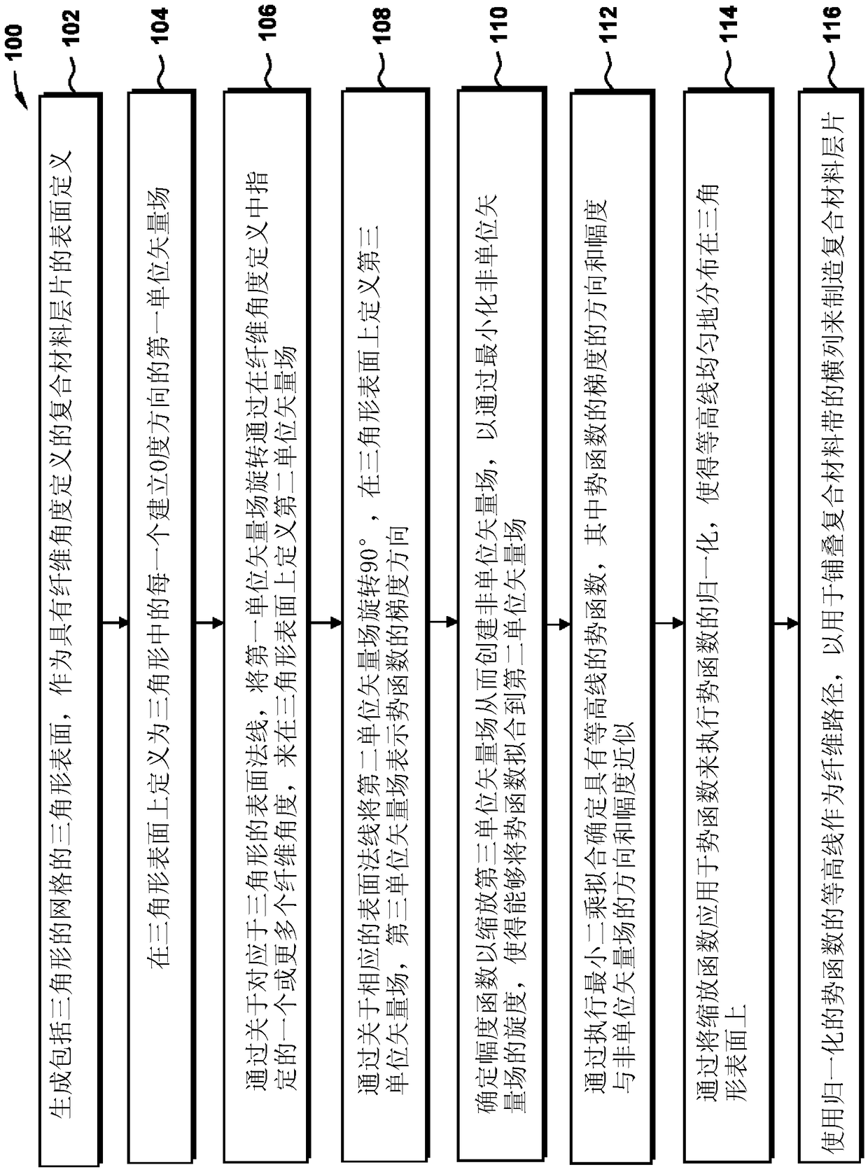
[0173] Embodiment 1. A method of determining the direction and spacing of fiber paths of a composite ply of a composite layup, taking into account surface definitions and fiber angle definitions having one or more fiber angles, comprising the steps of:

[0174] generating a surface approximation of the surface definition comprising a triangular surface, the triangular surface comprising a triangular mesh, the composite ply having at least one of the following characteristics: the surface definition has a non-planar profile, the fiber angle definition Contains non-constant fiber angles;

[0175] defining for each triangle a first unit vector field on the triangular surface that establishes a 0 degree direction from which one or more fiber angles are measured;

[0176] A second unit vector field is defined on the triangular surface by rotating the first unit vector field through the one or more fiber angles specified in the fiber angle definition with respect to the surface norm...

Embodiment 2

[0182] Embodiment 2. the method as described in embodiment 1, also comprises the following steps:

[0183] determining a second potential function that scales the third unit vector field by minimizing the deviation between the direction of the non-unit vector field and the direction of the gradient of the potential function while also adjusting the magnitude function , to improve the alignment of the contour lines with the second unit vector field.

Embodiment 3

[0184] Embodiment 3. the method as described in embodiment 1, also comprises the following steps:

[0185] determining a third potential function that improves the contour line from the second unit by minimizing only the deviation between the direction of the third unit vector field and the gradient direction of the potential function Alignment of vector fields.


PUM


Abstract

A method (100) of determining fibers paths (314) for a composite material layer sheet (202) includes generating a triangulated surface (218) of the composite material layer sheet (202), and defining afirst unit vector field establishing a 0-degree direction (302) for the triangulated surface. A second unit vector field (306) is defined by rotating, through specified fiber angles measured relativeto the 0-degree direction, the first unit vector field about surface normals of the triangulated surface. A third unit vector field representing a gradient direction (308) of a potential function isdefined by rotating the second unit vector field over 90D about the respective surface normals. The third unit vector field is scaled to create a non-unit vector field, and a first potential functionis determined by performing a least-squares fit such that the direction and magnitude of the gradient best approximate the direction and the magnitude of the non-unit vector field. A normalization ofthe potential function uniformly distributes contour lines of the potential function across the triangulated surface. The contour lines are used as fiber paths for laying up courses of composite material to fabricate the composite material layer sheet (202).

Description

technical field [0001] The present disclosure relates generally to composite manufacturing and, more particularly, to systems and methods for determining the direction and spacing of fiber paths for laying up composite tows to form composite plies. Background technique [0002] The design of the composite laminate includes specifying one or more fiber angles for each composite ply in the composite laminate. For example, a structural design engineer may specify fiber angles for each composite ply measured relative to a reference direction on the surface of the composite ply. For visualization and use in computational algorithms such as stress analysis software programs, the fiber angles can be represented by a vector field on the surface of a composite ply. To fabricate composite plies, manufacturing engineers can model fiber angles as continuous fiber paths when programming automated lay-up equipment. For example, an automated fiber placement machine (AFPM) may be programm...

Claims


Application Information

Patent Timeline
Patent Type & Authority Applications(China)
IPC IPC(8): G06F17/50B29C70/38
CPCB29C70/382G06F30/20G01N33/367G06F2113/26G06F2113/24G06F2119/18G06F30/15G06F2111/10G06F17/10B29C70/386B29K2105/0881G01B21/16
Inventor T·温弗利A·W·B-希伯
Owner THE BOEING CO
Why Eureka
Try Eureka