Battery module and manufacturing method thereof

A technology of battery module and manufacturing method, which is applied in secondary battery manufacturing, batteries, secondary batteries, etc., can solve problems such as bolt deformation, and achieve the effects of reducing weight, alleviating stress concentration, and improving rigidity

Inactive Publication Date: 2019-01-04
HONDA MOTOR CO LTD
View PDF7 Cites 3 Cited by
  • Summary
  • Abstract
  • Description
  • Claims
  • Application Information

AI Technical Summary

Problems solved by technology

In this structure, the load in the stacking direction of the single cells due to the expansion of the single cells acts concentratedly on the bolt fastening part, so there is a possibility that the bolt fastening part may slip or the bolt may be deformed.

Method used


Image

  • Battery module and manufacturing method thereof
  • Battery module and manufacturing method thereof
  • Battery module and manufacturing method thereof

Examples


no. 1 approach

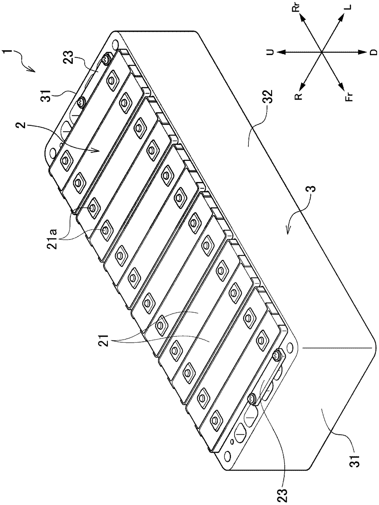
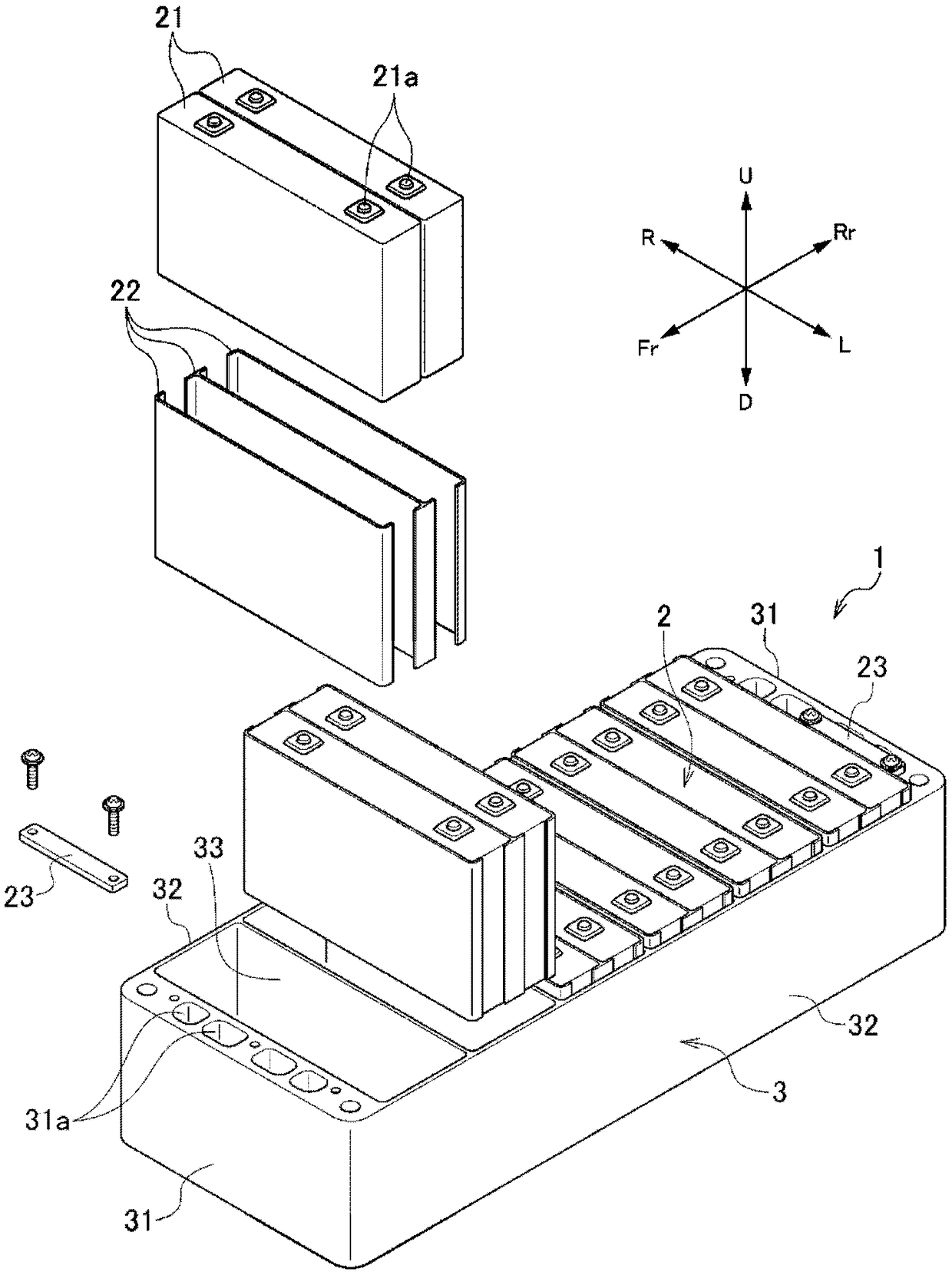
[0083] Such as Figure 1 to Figure 4 As shown, the battery module 1 according to the first embodiment of the present invention includes a single cell stack 2, which is formed by stacking a plurality of single cells 21 in the front-rear direction, and has a front surface, a rear surface, a left surface, a right surface, an upper surface, and a lower surface; and a case 3 that accommodates the cell stack 2 .

[0084] It should be noted that, in this specification and the like, for the sake of simplicity and clarity of description, the stacking direction of the cells 21 is defined as the front-rear direction, and the direction perpendicular to the stacking direction of the cells 21 is defined as the left-right direction and the up-down direction, The front-back direction of the product on which the battery module 1 is mounted is not relevant. That is, when the battery module 1 is mounted on a vehicle, the stacking direction of the cells 21 may coincide with the front-rear direct...

no. 2 approach

[0107] Next, refer to Figure 5 and Image 6 A battery module according to a second embodiment of the present invention will now be described. However, only the points of difference from the first embodiment will be described, and the description of the first embodiment will be referred to by using the same reference numerals as those of the first embodiment for the configurations common to the first embodiment.

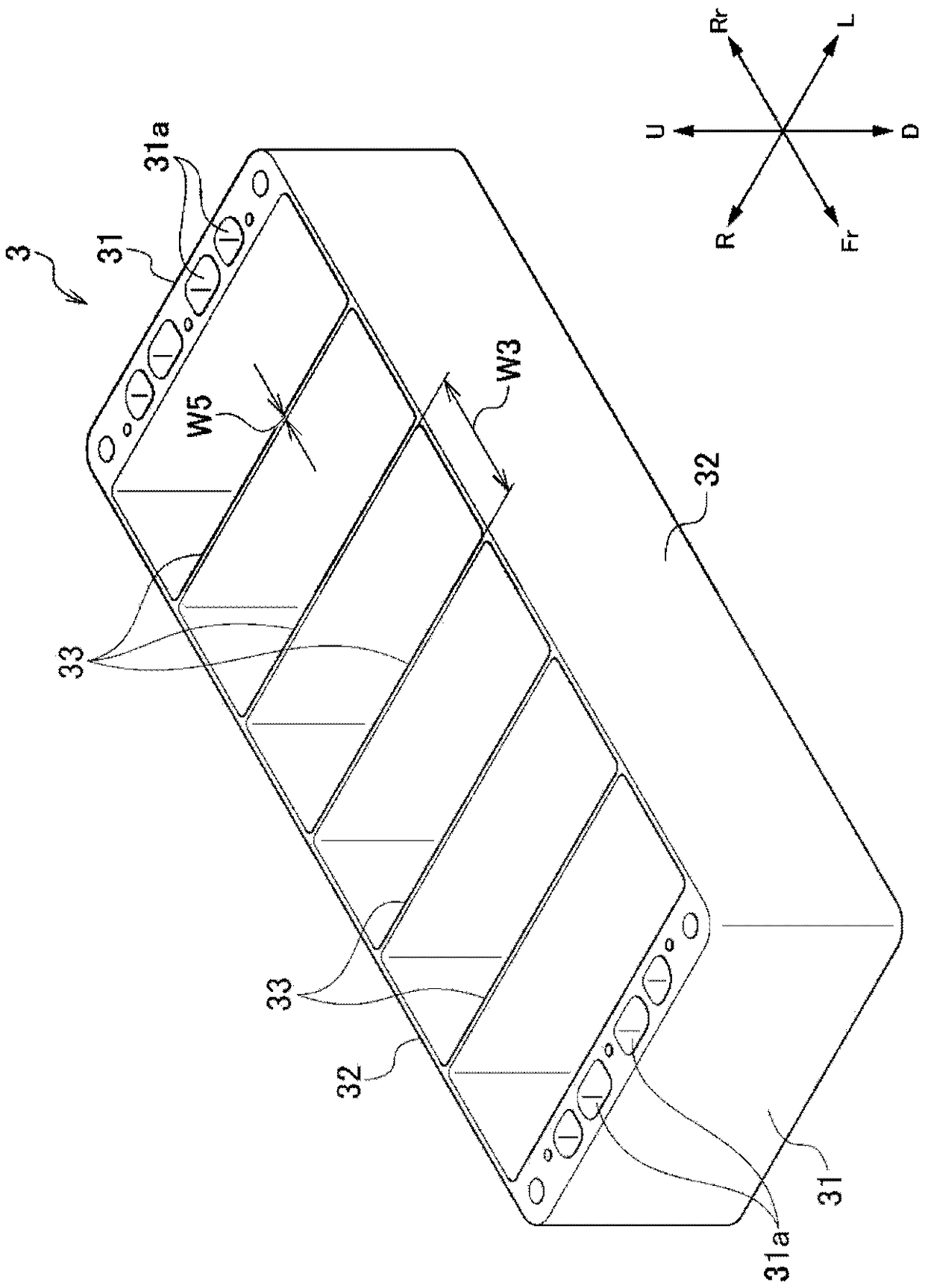
[0108] Such as Figure 5As shown, the battery module 1B according to the second embodiment differs from the first embodiment in that a bridge portion connecting the pair of side portions 32B to each other is not formed in the case 3B. It should be noted that, in Figure 5 In , the cell stack 2 is omitted.


PUM


Abstract

The invention provides a battery module capable of mitigating concentration of stress and receiving a load in a cell stacking direction caused by expansion of a unit cell, and a method of manufacturing the same. The battery module 1 includes: a cell stack body 2 that is constituted by a plurality of cells 21 stacked in a front-rear direction and includes a front surface, a rear surface, a left surface, a right surface, an upper surface, and a lower surface; and a casing 3 that accommodates the cell stack body 2. In the battery module, the casing 3 includes: a pair of end portions 31 extendingalong the front surface and the rear surface of the cell stack body 2; and a side portions 32 extending along the left surface and the right surface of the cell stack body 2. A width W1 in the front-rear direction of the end portion is larger than a width W2 in the left-right direction of the side portion 32.

Description

technical field [0001] The present invention relates to a battery module mounted on an electric vehicle and a method for manufacturing the same. Background technique [0002] Conventionally, electric vehicles and the like are equipped with battery modules. For example, Patent Documents 1 and 2 disclose a battery module including a battery cell stack formed by stacking a plurality of battery cells in the front-rear direction, and having a front surface, a rear surface, a left surface, and a right surface. , an upper surface and a lower surface; a pair of end plates disposed on the front and rear surfaces of the single cell stack; and a fastening frame connecting the pair of end plates. [0003] In such a battery module, a load in the cell lamination direction of the battery module (hereinafter appropriately referred to as a cell thickness constraint reaction force) occurs due to expansion of the cells due to temperature changes and aging deterioration. In recent years, with...

Claims


Application Information

Patent Timeline
Patent Type & Authority Applications(China)
IPC IPC(8): H01M2/10H01M10/04H01M50/209H01M50/224H01M50/289H01M50/296H01M50/55H01M50/553
CPCH01M10/0413H01M50/296H01M50/289H01M50/553H01M50/209H01M50/224H01M50/55B60L50/64H01M10/0481H01M2220/20B21C23/142Y02T10/70Y02E60/10Y02P70/50
Inventor 樱井敦
Owner HONDA MOTOR CO LTD
Why Eureka
Try Eureka