
A radome for a multifunctional base station antenna

A technology of base station antenna and radome, applied in the field of radome, can solve problems such as economic loss, affecting product development efficiency, etc., to reduce the impact, optimize the antenna radiation performance, and solve the effect of the poor front-to-back ratio of the antenna.

Inactive Publication Date: 2019-01-04
ZHONGTIAN BROADBAND TECH +1
View PDF6 Cites 2 Cited by
  • Summary
  • Abstract
  • Description
  • Claims
  • Application Information

AI Technical Summary

Problems solved by technology

The current radome adopts a closed, fixed-shaped section, and an integrally formed cylindrical radome, and the wave transmission performance in all directions is consistent; if the radome performance cannot meet the product design index requirements, it is necessary to redesign the radome. On the one hand, it affects the efficiency of product research and development, and on the other hand, it causes economic losses

Method used


Image

  • A radome for a multifunctional base station antenna
  • A radome for a multifunctional base station antenna
  • A radome for a multifunctional base station antenna

Examples


Embodiment 1

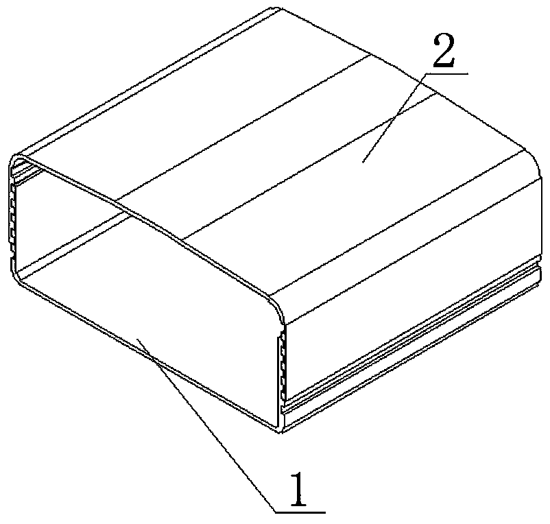
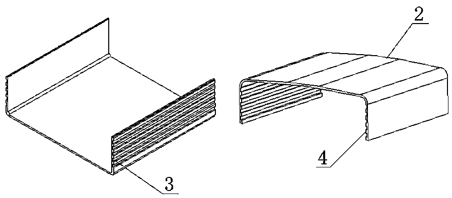
[0027] Such as figure 1 , 2 , 3, the radome of a multifunctional base station antenna of the present invention includes a bottom cover 1 and a top cover 2, and the two ends of the bottom cover 1 and the top cover 2 are overlapped and clamped by a clamping structure to form a complete The cylinder radome, the clamping structure is that there are several grooves 3 arranged along the edge direction of the end of the bottom cover on the outer surface of the two ends of the bottom cover 1, and at least one groove 3 is arranged on the inner surface of the two ends of the top cover 2. The raised strip 4 matching the groove 3, when the top cover 2 is covered on the outside of the bottom cover 1, the raised strip 4 selects the groove 3 at a different position and is stuck in the groove 3, thereby realizing different radome Variation in section height.

[0028] The groove 3 is a strip-shaped groove and the opening edge of the groove 3 is provided with chamfers or rounded corners. The ...

Embodiment 2

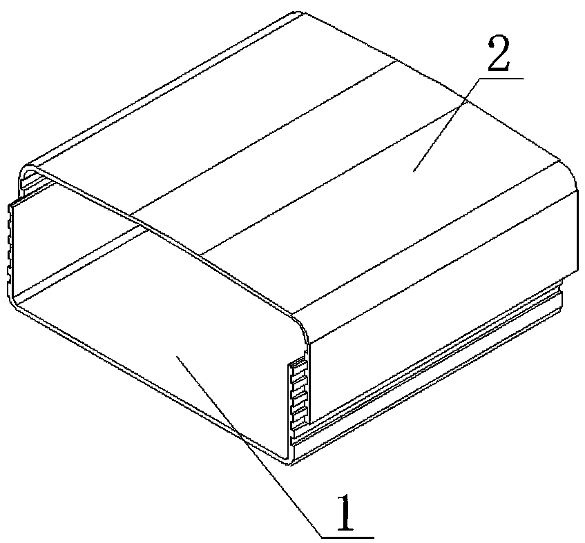
[0031] Such as Figure 4 , 5 As shown in , 6, a radome of a multifunctional base station antenna includes a bottom cover 1 and a top cover 2, and the two ends of the bottom cover 1 and the top cover 2 are overlapped and clamped by a clamping structure to form a complete cylinder antenna The cover, the clamping structure is that there are several grooves 3 arranged along the edge direction of the end of the bottom cover on the inner surface of the two ends of the bottom cover 1, and at least one groove 3 is arranged on the outer surface of the two ends of the top cover 2. 3. Matching convex strip 4, when the top cover 2 is clamped inside the bottom cover 1, the convex strip 4 is clamped in the groove 3.

[0032] The groove 3 is an elongated groove, and the groove 3 is a T-shaped groove or a dovetail groove, and the shape of the protruding strip 4 matches the shape of the groove 3 . When the protruding strip 4 is clamped in the groove 3, the groove 3 is provided with an adhesi...


PUM


Abstract

The invention discloses a radome of a multifunctional base station antenna, comprising a bottom cover and a top cover, the two end portions of the bottom cover and the top cover are mutually overlapped and clamped by a clamping structure to form a complete cylindrical radome, The clamping structure is that a plurality of grooves are arranged along the direction of the end edges of the bottom coveron the outer sides of both end portions of the bottom cover, and at least one convex strip matched with the groove is arranged on the inner sides of both end portions of the top cover. When the top cover is arranged on the outer sides of the bottom cover, the convex strip selects the grooves at different positions and is clamped in the grooves. Or the top cover is clamped on the inside of the bottom cover. As that combine radome is adopted, the cross-sectional size of the radome can be changed, the influence of the radome on the antenna radiation performance can be reduced, and the antenna radiation performance can be optimized.

Description

technical field [0001] The invention relates to a radome, in particular to a radome of a multifunctional base station antenna. Background technique [0002] The radome is used as a protective part of the antenna. Its function is to protect the internal components of the antenna from external factors, and to have good wave-transmitting performance to reduce the impact on the external radiation performance of electromagnetic waves. Since the front of the radome is in the near-field area of ​​the radiation direction, the radome is placed on the front of the radiation field as a dielectric material, and the distance between it and the radiation unit (vibrator) will affect the electrical performance of the antenna (VSWR, port isolation) degrees, etc.), radiation characteristics have an impact. The current radome adopts a closed, fixed-shaped section, and an integrally formed cylindrical radome, and the wave transmission performance in all directions is consistent; if the radome ...

Claims


Application Information

Patent Timeline
Patent Type & Authority Applications(China)
IPC IPC(8): H01Q1/42
CPCH01Q1/42
Inventor 谷宝生符小东王学仁张闪光徐翠丁建军吴海龙靳志尧蒋鹏飞
Owner ZHONGTIAN BROADBAND TECH
Learn More