
Small Dual Circularly Polarized Antenna Based on High and Low Frequency Multiplexing

A dual circular polarization, high and low frequency technology, applied to antenna unit combinations with different polarization directions, independent antenna unit combinations, antennas, etc., can solve the problem of large volume of dual circularly polarized antennas, and achieve improved gain and orientation performance, improve axial ratio and gain, and reduce the effect of mutual influence

Active Publication Date: 2018-12-21
西安雷远电子科技有限公司
View PDF4 Cites 0 Cited by
  • Summary
  • Abstract
  • Description
  • Claims
  • Application Information

AI Technical Summary

Problems solved by technology

[0004] The purpose of the present invention is to overcome the defects of the above-mentioned prior art, and propose a small dual circularly polarized antenna based on high and low frequency multiplexing, which is used to solve the problem of dual circular polarization in the existing U / S frequency bands (340-400MHz and 1900-2300MHz). The problem of large size of circularly polarized antenna

Method used


Image

  • Small Dual Circularly Polarized Antenna Based on High and Low Frequency Multiplexing
  • Small Dual Circularly Polarized Antenna Based on High and Low Frequency Multiplexing
  • Small Dual Circularly Polarized Antenna Based on High and Low Frequency Multiplexing

Examples


Embodiment Construction

[0024] Below in conjunction with accompanying drawing and embodiment, the present invention will be further described:

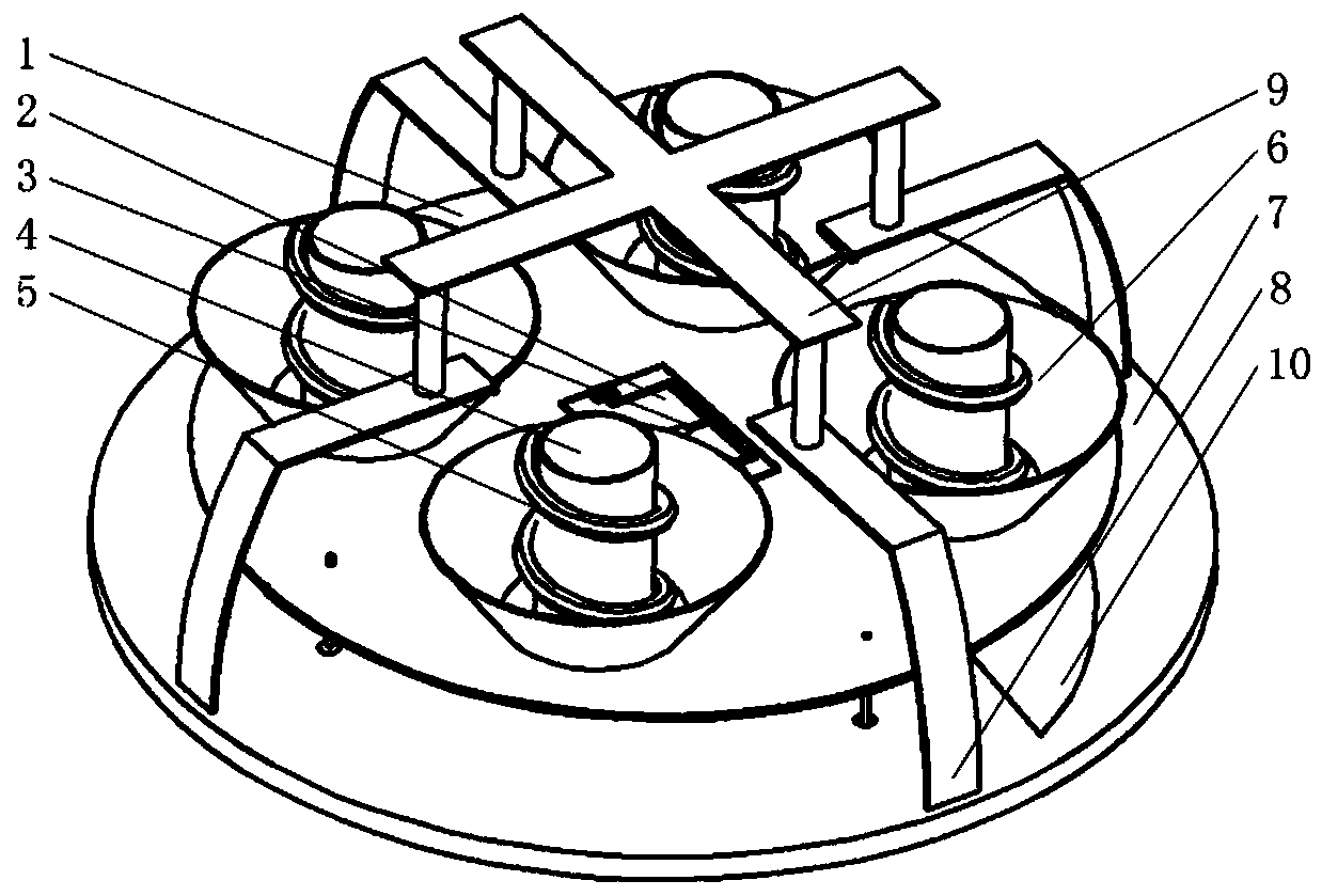
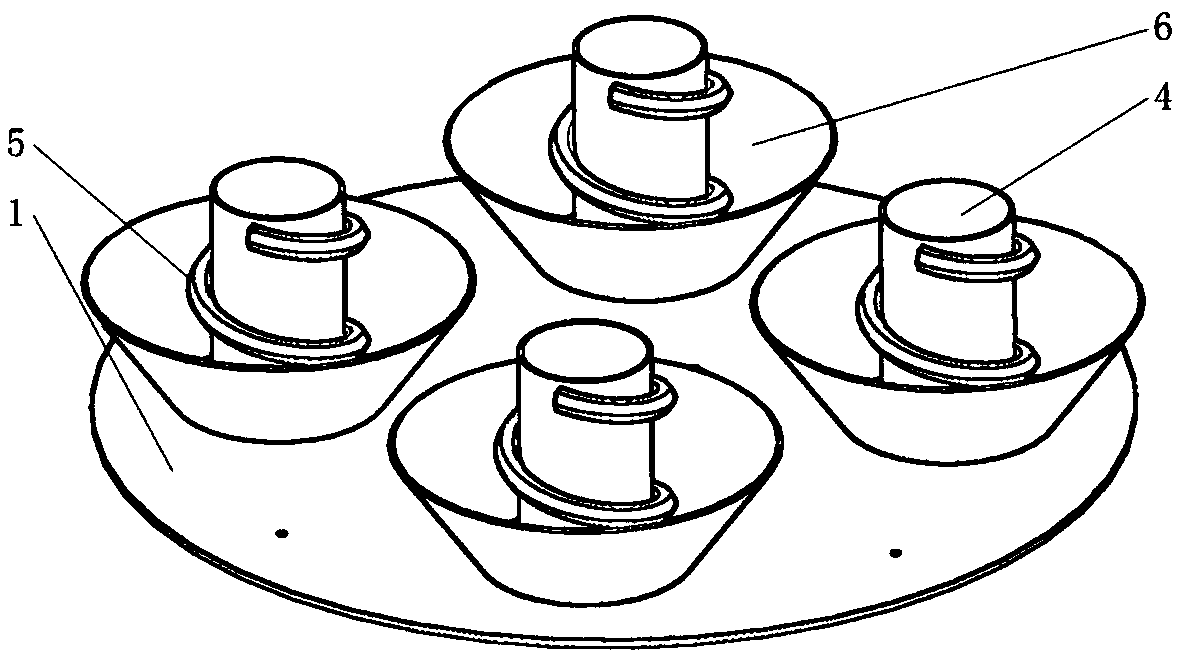
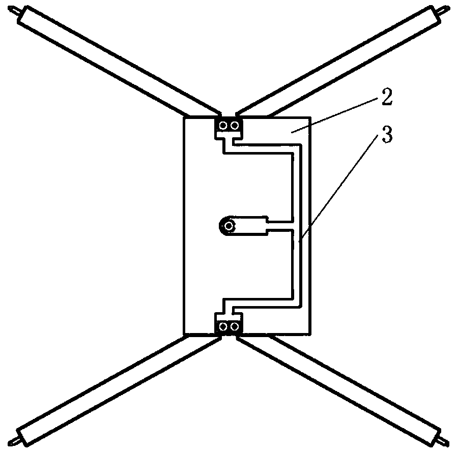
[0025] refer to figure 1 , the present invention includes a low-frequency radiator and a high-frequency radiator, and the low-frequency radiator adopts a thin metal plate. In this embodiment, the thin metal plate adopts a circular aluminum plate with a thickness of 2mm and a radius of 132mm, and a first dielectric plate is fixed on its upper surface And 2×2 high-frequency radiators, the form of four high-frequency radiation unit arrays can improve the gain of the antenna in the high-frequency band, wherein the first dielectric plate is located in the center of the upper surface of the metal sheet, and the 2×2 high-frequency radiation The center of the mouth surface of the body coincides with the center of the upper surface of the metal sheet; the upper surface of the first dielectric plate is printed with a high-frequency feed network, wherein the high-frequ...


PUM


Abstract

The invention provides a micro dual-circular-polarization antenna based on high low frequency multiplexing and aims to solve a technical problem of relatively large volume of a U / S wave band dual-circular-polarization antenna in the prior art. The micro dual-circular-polarization antenna comprises a thin metal plate, a first medium plate, 2*2 high frequency radiators, a bottom plate, four parasitic branches, a director and second and third medium plates, wherein each high frequency radiator comprises a high frequency radiation unit, a medium sleeve and a reflection plate, the first medium plate and the 2*2 high frequency radiators are fixed on the upper surface of the thin metal plate, the bottom plate is arranged below the thin metal plate through a supporting device, the second medium plate and the four 90-DEG rotary symmetrical gamma-shaped parasitic branches are fixed on the upper surface of the bottom plate, the third medium plate is fixed on the lower surface of the bottom plate, and the director is fixed at a top end of the gamma-shaped parasitic branches through an insulation supporting column. The micro dual-circular-polarization antenna is advantaged in that the volume is small, dual-circular-polarization characteristics can be realized, and the micro dual-circular-polarization antenna can be applied to signal reception and transmission of satellite communication shipborne systems.

Description

technical field [0001] The invention belongs to the technical field of antennas, and relates to a dual circularly polarized antenna, in particular to a small dual circularly polarized antenna working in the U / S frequency band based on high and low frequency multiplexing, which can be used for satellite communications (340-400MHz and 1900 ~ 2300MHz) signal reception and transmission of the shipboard system. Background technique [0002] Satellite communication system refers to the communication system between radio communication stations on the earth using satellites as relays. It has played an important role in different fields such as military and civilian use, and has become an indispensable radio application technology. In modern wireless communication systems, U-band has an extremely wide range of applications, especially in military applications. U-band has been recognized by various countries for its advantages of strong signal penetration, strong terminal practicabili...

Claims


Application Information

Patent Timeline
Patent Type & Authority Patents(China)
IPC IPC(8): H01Q1/36H01Q1/50H01Q19/13H01Q21/00H01Q21/24H01Q21/30
CPCH01Q1/36H01Q1/50H01Q19/132H01Q21/0006H01Q21/24H01Q21/30
Inventor 翁子彬杜若楠张立焦永昌杨磊
Owner 西安雷远电子科技有限公司
Learn More