1*8 broadband beam fixed traveling wave antenna

A traveling-wave antenna and beam technology, applied in the field of communication antennas, can solve problems such as complex antenna design, and achieve the effect of easy integration and processing

Active Publication Date: 2021-05-07
SUN YAT SEN UNIV
View PDF7 Cites 0 Cited by
  • Summary
  • Abstract
  • Description
  • Claims
  • Application Information

AI Technical Summary

Problems solved by technology

Some leaky-wave antennas can also be regarded as series-fed array antennas, but there will be beam dispersion. The methods to reduce beam dispersion and achieve beam fixation include coupled substrate-integrated waveguide antennas, metamaterial antennas, and metasurface antennas. However, the design of these antennas is more complicated
[0003] The publication date is November 24, 2017, and the Chinese patent with the publication number CN107394381A discloses a low-profile broadband circularly polarized array antenna based on stacked traveling wave antenna units, including: three segments connected end to end and printed on both sides of the dielectric board Circularly polarized antenna unit composed of the metal layer on the side and metallized through-holes connecting the two layers, 2×2 antenna sub-array composed of metallized through-hole cavity and 4 antenna units, 16 antenna sub-array composed of metalized through-holes The full parallel feed network, the gap between the feed layer and the metal cavity and the antenna for coupling feed, the grounded coplanar waveguide (Grounded Coplanar Waveguide, GCPW) and the substrate integrated waveguide (Substrate Integrated Waveguide, SIW), but the design of the antenna is more complicated

Method used


Image

  • 1*8 broadband beam fixed traveling wave antenna
  • 1*8 broadband beam fixed traveling wave antenna
  • 1*8 broadband beam fixed traveling wave antenna

Examples


Embodiment 1

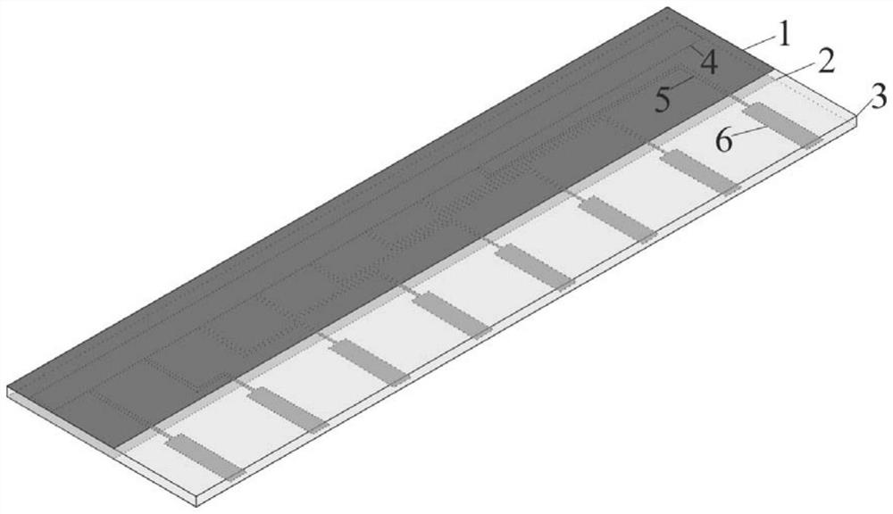
[0034] This embodiment provides a 1×8 broadband beam fixed traveling wave antenna, such as Figures 1 to 3 , including an upper metal plate 1, a lower metal plate 2, a dielectric plate 3, a main feeder 4, 8 branches 5 and 8 radiation patches 6, where:

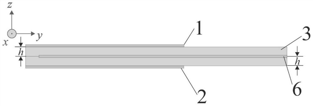
[0035] The upper metal plate 1, the lower metal plate 2 and the medium plate 3 are all strip-shaped, the upper metal plate 1 is attached to the upper surface of the medium plate 3, and the lower metal plate 2 is attached to the medium the lower surface of the plate 3;

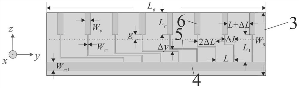
[0036] The dielectric board 3 has an intermediate layer, the main feeder 4, 8 branches 5 and 8 radiation patches 6 are arranged in the intermediate layer, the main feeder 4 is arranged along the length direction of the dielectric board 3, The eight branches 5 are connected to the main feeder 4, the eight branches 5 are arranged along the width direction of the dielectric board 3, the eight branches 5 have length differences, and the eight radiation patches 6 ar...


PUM


Abstract

The invention provides a 1*8 broadband beam fixed traveling wave antenna which comprises an upper layer metal plate, a lower layer metal plate, a dielectric plate, a main feeder line, 8 branches and 8 radiation patches. The upper layer metal plate, the lower layer metal plate and the dielectric plate are strip-shaped, the upper layer metal plate is attached to the upper surface of the dielectric plate, and the lower-layer metal plate is attached to the lower surface of the dielectric plate; the dielectric plate is provided with a middle layer, the middle layer is internally provided with the main feeder line, the 8 branches and the 8 radiation patches, the main feeder line is arranged along the length direction of the dielectric plate, the 8 branches are connected with the main feeder line, the 8 branches are arranged along the width direction of the dielectric plate, the 8 branches have a length difference, and the 8 radiation patches are connected with one branch. A printed circuit board technology can be adopted in the structure, the antenna is easy to integrate and process, and meanwhile the radiation characteristic of fixed wave beams is achieved through the length difference of the 8 branches.

Description

technical field [0001] The invention relates to the field of communication antennas, in particular to a 1×8 broadband beam fixed traveling wave antenna. Background technique [0002] The fixed beam antenna is a commonly used antenna in wireless communication. It can radiate in a fixed direction and can be used in satellite communication and point-to-point communication. Traditional antennas that can achieve fixed beams include series-fed array antennas. Some leaky-wave antennas can also be regarded as series-fed array antennas, but there will be beam dispersion. The methods to reduce beam dispersion and achieve beam fixation include coupled substrate-integrated waveguide antennas, metamaterial antennas, and metasurface antennas. However, the design of these antennas is relatively complicated. [0003] The publication date is November 24, 2017, and the Chinese patent with the publication number CN107394381A discloses a low-profile broadband circularly polarized array antenn...

Claims


Application Information

Patent Timeline
Patent Type & Authority Applications(China)
IPC IPC(8): H01Q1/38H01Q1/50H01Q21/06
CPCH01Q1/38H01Q1/50H01Q21/065
Inventor 刘菊华蔡双棋
Owner SUN YAT SEN UNIV
Why Eureka
Try Eureka