Millimeter wave packaging antenna based on LTCC and array antenna

A millimeter-wave and antenna technology, applied in antenna arrays, antennas, antenna coupling, etc., can solve problems such as large volume, high cost, and complex antenna stacking structure

Pending Publication Date: 2021-04-30
COMBA TELECOM SYST CHINA LTD
View PDF0 Cites 0 Cited by
  • Summary
  • Abstract
  • Description
  • Claims
  • Application Information

AI Technical Summary

Problems solved by technology

However, the stacked structure of the traditional 5G millimeter-wave single-polarization array antenna is relatively complex, with high cost and large volume

Method used


Image

  • Millimeter wave packaging antenna based on LTCC and array antenna
  • Millimeter wave packaging antenna based on LTCC and array antenna
  • Millimeter wave packaging antenna based on LTCC and array antenna

Examples


Embodiment Construction

[0036] In order to make the above objects, features and advantages of the present invention more comprehensible, specific implementations of the present invention will be described in detail below in conjunction with the accompanying drawings. In the following description, numerous specific details are set forth in order to provide a thorough understanding of the present invention. However, the present invention can be implemented in many other ways different from those described here, and those skilled in the art can make similar improvements without departing from the connotation of the present invention, so the present invention is not limited by the specific embodiments disclosed below.

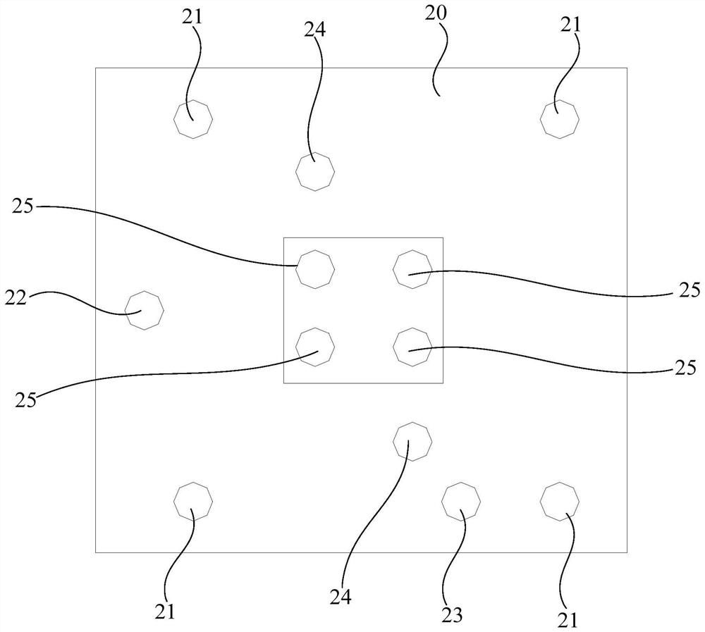
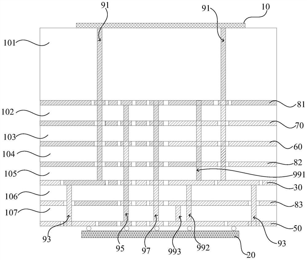
[0037] refer to figure 1 and figure 2 , figure 1 A schematic structural diagram of a beamforming chip 20 of an LTCC-based millimeter-wave packaged antenna according to an embodiment of the present invention is shown; figure 2 A schematic cross-sectional view of an LTCC-based millimet...


PUM


Abstract

The invention relates to a millimeter wave packaging antenna based on LTCC and an array antenna; a first ground layer serves as the reference ground layer of a radiation unit layer, and provides a reference ground plane for the radiation unit layer, so as to achieve the radiation characteristics of an antenna unit; a second ground layer can realize mutual isolation of the control signal layer and the first radio frequency circuit layer; and a third ground layer can realize mutual isolation of the first radio frequency circuit layer and the second radio frequency circuit layer, and is also a reference ground plane of the first radio frequency circuit layer and the second radio frequency circuit layer. The millimeter wave packaging antenna based on LTCC can realize input and output of radio frequency signals of the radiation unit layers of the multilayer circuit board designed based on LTCC, can be suitable for production and manufacturing of LTCC technology with mature technology, and is low in cost, small in size and light in weight.

Description

technical field [0001] The invention relates to the technical field of communication antennas, in particular to an LTCC-based millimeter-wave package antenna and an array antenna. Background technique [0002] With the development of 5G communication technology, in order to overcome the shortage of sub-6G spectrum resources, millimeter wave has significant advantages in large bandwidth and high-speed communication. However, in the 5G millimeter wave frequency band, the electromagnetic wave signal has a large space loss and a short propagation path. [0003] The traditional 5G millimeter-wave single-polarization array antenna uses two array antennas with different polarizations to meet the requirements of MIMO communication in hybrid-Beamforming (hybrid beamforming) application scenarios. LTCC (Low Temperature Co-fired Ceramic) is usually used. Fired ceramics) process. However, the stacked structure of the traditional 5G millimeter-wave single-polarization array antenna is ...

Claims


Application Information

Patent Timeline
Patent Type & Authority Applications(China)
IPC IPC(8): H01Q1/38H01Q1/48H01Q1/52H01Q21/00
CPCH01Q1/38H01Q1/48H01Q1/52H01Q21/00
Inventor 高永振杨波伍尚坤高霞朱继宏王彪张志梅邱诗彬
Owner COMBA TELECOM SYST CHINA LTD
Why Eureka
Try Eureka