
Switching control method and device

A control method and technology before switching, applied in the direction of using the return channel for error prevention/detection, digital transmission system, electrical components, etc., can solve the problem of terminal equipment lost data packets, lost data packets, data packets retransmitted to terminal equipment, etc. problem, to achieve the effect of saving system resources, reducing air interface overhead, and lossless switching

Active Publication Date: 2019-01-04
HUAWEI TECH CO LTD
View PDF2 Cites 12 Cited by
  • Summary
  • Abstract
  • Description
  • Claims
  • Application Information

AI Technical Summary

Problems solved by technology

Due to SN reconfiguration, some data packets sent by the source base station to the terminal device before the handover and not correctly received by the terminal device cannot be retransmitted to the terminal device at the target base station, causing the terminal device to lose data packets during the handover process
In another case, when the configurations of the source base station and the target base station are different, for example, the protocol versions supported by the source base station and the target base station are different, so that the target base station cannot recognize some configuration information of the source base station, which will also cause the target base station to switch the terminal equipment Afterwards, the SN of all data packets processed by the PDCP entity communicated with the target base station is reconfigured, also known as full configuration (full configuration)
In this case, it will also cause the end device to lose packets during the handover process
[0006] There is currently no suitable solution for how to realize the lossless handover of the terminal equipment in the above scenario and ensure that the terminal equipment does not lose data packets during the handover process.

Method used


Image

  • Switching control method and device
  • Switching control method and device
  • Switching control method and device

Examples


Embodiment Construction

[0080] The embodiments of the present application will be described below with reference to the drawings in the embodiments of the present application.

[0081]In this application, the word "exemplary" is used to mean "serving as an example, illustration or illustration". Any embodiment described in this application as "exemplary" is not necessarily to be construed as preferred or advantageous over other embodiments. The following description is given to enable any person skilled in the art to make and use the invention. In the following description, details are set forth for purposes of explanation. It should be understood that one of ordinary skill in the art would recognize that the present invention may be practiced without the use of these specific details. In other instances, well-known structures and procedures are not described in detail to avoid obscuring the description of the present invention with unnecessary detail. Thus, the present invention is not intended t...


PUM


Abstract

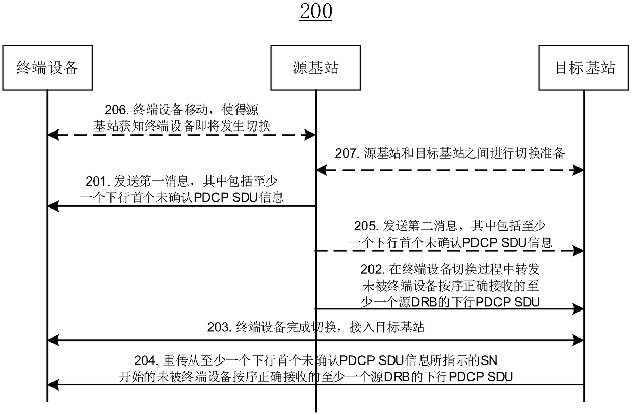
The invention provides a switching control method and device. The method comprises the following steps: the source base station sends a message used for instruction switching to terminal equipment, wherein the message includes at least one downlink first unacknowledged PDCP SDU information; the source base station sends the PDCP SDU of at least one source DRB which is not sequentially and correctly received by the terminal equipment to the target base station in the switching process of the terminal equipment; and after the terminal equipment completes the switching access to the target base station, the target base station resends the downlink PDCP SDU of the at least one source DRB which is not correctly received by the terminal equipment and starts from the SN and is indicated by at least one downlink first unacknowledged PDCP SDU information to the terminal equipment. With application of the switching control method, lossless switching of the terminal equipment in the moving process can be realized, and the business service quality of the terminal equipment in the switching process can be effectively guaranteed.

Description

technical field [0001] The present invention relates to the field of wireless communication, in particular to a switching control method and device. Background technique [0002] In the Long Term Evolution (LTE) system, the data plane protocol layer of the air interface includes packet data convergence protocol (PDCP) layer, radio link control (radio link control, RLC), Media access control (media access control, MAC) layer and physical (PHY) layer. For the downlink data packet, the core network equipment filters the data packet according to its quality of service (QoS) attribute and maps it to a bearer, and then transmits it to the base station, and the base station then sends the data packet to the terminal device with the same bearer. [0003] With the rapid development of wireless communication technology, the fifth generation (5th Generation, 5G) wireless communication technology has become a hot spot in the industry at present. A new service data adaptation protocol ...

Claims


Application Information

Patent Timeline
IPC IPC(8): H04W36/00H04L1/18H04L1/16
CPCH04L1/1607H04L1/18H04W36/0011H04W36/08H04W36/0235H04W36/0064H04L47/34H04L1/08
Inventor 晋英豪杨阳李宏韩锋
Owner HUAWEI TECH CO LTD
Learn More