Test device and method for explosive forming of metal slotted pipe

A technology of explosive forming and experimental device, applied in the direction of material explosiveness

Active Publication Date: 2019-01-08
CHINA UNIV OF PETROLEUM (BEIJING)
View PDF10 Cites 0 Cited by
  • Summary
  • Abstract
  • Description
  • Claims
  • Application Information

AI Technical Summary

Problems solved by technology

However, the downhole is high temperature and high pressure, and the experimental results under normal temperature and pressure are quite different from the downhole working conditions.

Method used


Image

  • Test device and method for explosive forming of metal slotted pipe
  • Test device and method for explosive forming of metal slotted pipe
  • Test device and method for explosive forming of metal slotted pipe

Examples


Embodiment approach 1

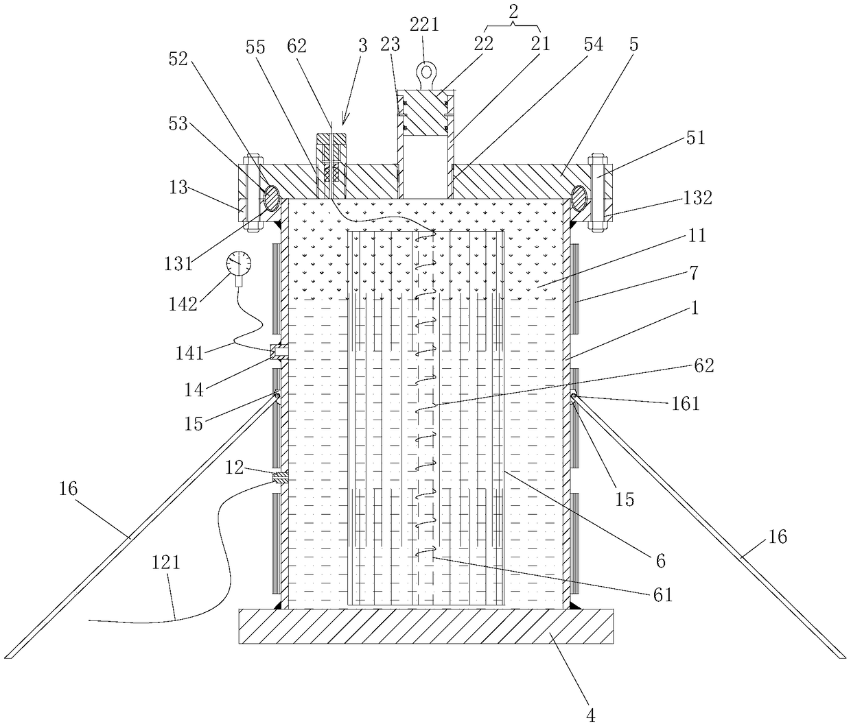
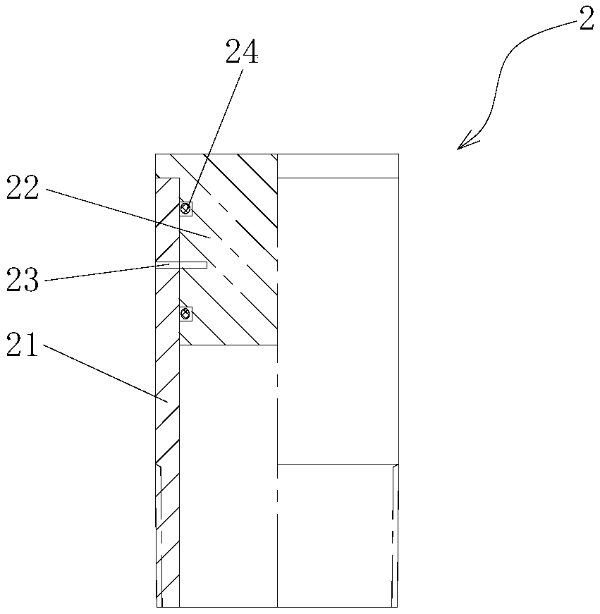
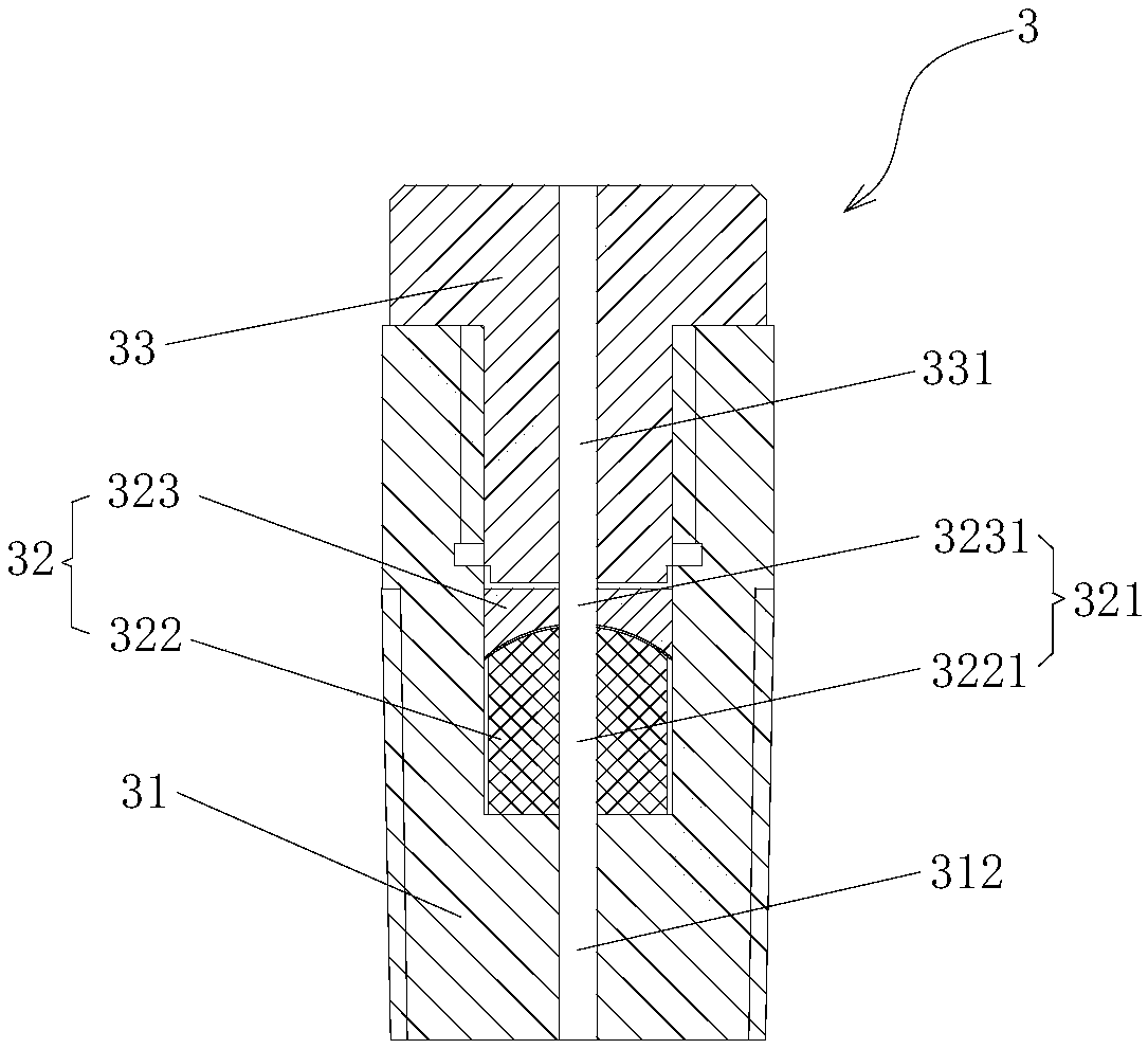
[0040] Such as figure 1 As shown, the present invention provides a metal slotted pipe explosive forming experiment device, comprising a target cylinder 1, a pressure relief valve 2 and a detonating cord sealing sleeve 3, wherein: the lower end of the target cylinder 1 is sealed and connected with a bottom flange 4, Its upper end is detachably sealed with a top flange 5, the target cylinder 1 has an inner cavity 11 capable of accommodating the metal slotted pipe 6, and the target cylinder 1 is provided with a pressurized joint 12, the pressurized joint 12 It communicates with the inner cavity 11, and the outer wall of the target cylinder 1 is provided with a heating belt layer 7; the pressure relief valve 2 is sealed and connected to the top flange 5, and the pressure relief valve 2 is connected with the inner cavity 11 are connected; the detonating cord sealing sleeve 3 is sealed and connected on the top flange 5, the metal slotted pipe 6 is provided with a detonating mandrel ...

Embodiment approach 2

[0055] Such as Figure 1 to Figure 8 As shown, the present invention also provides an experimental method for explosive forming of metal slotted pipe, which is implemented by using the experimental device for explosive forming of metal slotted pipe described in Embodiment 1. The experimental method for explosive forming of metal slotted pipe includes the following steps :

[0056] Step S1: Place the metal slotted tube 6 with the detonating mandrel 61 in the inner cavity 11 of the target cylinder 1, inject liquid into the inner cavity 11, and guide the detonating mandrel 61 The detonating cord 62 passes through the target cylinder 1 from the detonating cord sealing sleeve 3, and seals the top flange 5 at the upper end of the target cylinder 1;

[0057] Step S2: Inject an inert gas into the inner cavity 11 of the target cylinder 1 through the pressurized joint 12;

[0058] Step S3: heating the heating belt layer 7;

[0059] Step S4: ignite the detonating cord 62, detonate the...


PUM

PropertyMeasurementUnit
Shore hardnessaaaaaaaaaa

Abstract

The invention provides a test device and method for explosive forming of a metal slotted pipe. The test device comprises a target tube, a pressure relief valve and a detonating cord sealing sleeve; the lower end of the target tube is connected with a bottom flange in a sealed manner; the upper end of the target tube is detachably connected with a top flange in a sealed manner; the target tube comprises an inner cavity capable of accommodating the metal slotted pipe; a pressurizing joint is arranged on the target tube and communicates with the inner cavity; a heating band layer is arranged on the outer wall of the target tube; the pressure relief valve is connected onto the top flange in a sealed manner and communicates with the inner cavity; the detonating cord sealing sleeve is connectedonto the top flange in a sealed manner; a detonating mandrel is arranged inside the metal slotted pipe; and a detonating cord of the detonating mandrel can penetrates out of the target tube via the detonating cord sealing sleeve. By the aid of the test device and method for explosive forming of the metal slotted pipe, downhole conditions can be simulated relatively truly, and a test foundation canbe provided for explosive forming of the metal slotted pipe.

Description

technical field [0001] The invention relates to the technical field of karst cave plugging in underground construction, in particular to an experimental device and an experimental method for explosive forming of metal slotted pipes. Background technique [0002] In the process of oil drilling, sometimes karst caves are encountered, and for small karst caves, it is necessary to plug the leakage and continue drilling. One of the plugging methods is to put a metal pipe of appropriate length into the cave, then use explosives to explode it into a desired shape to form a skeleton, and then fill the gap with mud or cement slurry. [0003] But for different lengths, different outer diameters, different slit forms, single-layer or multi-layer metal pipes, the amount of explosives used is different, and the shape is also different. How to obtain the ideal shape corresponding to the amount of explosive used requires a lot of ground experiments. We conducted four experiments at norma...

Claims


Application Information

Patent Timeline
Patent Type & Authority Applications(China)
IPC IPC(8): G01N25/54
CPCG01N25/54
Inventor 张逸群刘亚李根生黄中伟季璐宋先知史怀忠盛茂
Owner CHINA UNIV OF PETROLEUM (BEIJING)
Why Eureka
Try Eureka